Search found 923 matches
- Sat Dec 22, 2018 1:47 pm
- Forum: 5-tube nixie clocks
- Topic: Options and mods
- Replies: 7
- Views: 38747
Re: Options and mods
This should have been the first post on this thread but has been deleted by mistake - GPS input - 5V TTL level serial data at 2400/4800/9600 BPS (auto detect). Wire up a jack plug for SK2 as follows: Tip - Ground Centre barrel - 5V Outer barrel - Data out from GPS. Fit wire links in places R14 (uppe...
- Mon Dec 17, 2018 8:35 pm
- Forum: Assembly Instructions for the IN-14 5-tube clock
- Topic: Operating instructions Button PCB
- Replies: 0
- Views: 14640
Operating instructions Button PCB
To enter menu mode you need fingers on both buttons - this is the '<' selection. When it beeps and displays 9-00 lift your left finger - this is the '>' selection. To change the display to minutes-seconds or date touch the right hand switch. Repeat to change modes, if left for about 10 seconds the d...
- Mon Dec 17, 2018 8:23 pm
- Forum: Assembly Instructions for the IN-14 5-tube clock
- Topic: 2- BUTTON version PCB assembly - Bag2
- Replies: 7
- Views: 17842
Re: BUTTON version PCB assembly - Bag2
Now carefully solder the switches onto the top of the pin strips. They'll need to be right at the top of them to be close to the case lid: http://www.lasermad.com/instructions/IN14%20BUTTON/in14buttonpcb1A.jpg Power up the board again and test the switches. They have a red LED that should light up w...
- Mon Dec 17, 2018 8:21 pm
- Forum: Assembly Instructions for the IN-14 5-tube clock
- Topic: 2- BUTTON version PCB assembly - Bag2
- Replies: 7
- Views: 17842
Re: BUTTON version PCB assembly - Bag2
Fit the 2x 3-pin strips from bag1 in the locations marked here. These are used to connect the touchswitch modules to the main PCB:

- Mon Dec 17, 2018 8:18 pm
- Forum: Assembly Instructions for the IN-14 5-tube clock
- Topic: 2- BUTTON version PCB assembly - Bag2
- Replies: 7
- Views: 17842
Re: BUTTON version PCB assembly - Bag2
Fit IC1 (PIC 16F1827) and IC2 (K155ID1) into their sockets and reconnect the multimeter and USB supply. Make sure both notches point towards D8, IC1 is 'upside down' relative to IC2. This time the current reading should be about 20-25mA and the 5 blue LEDs will light up, flickering slightly. http://...
- Mon Dec 17, 2018 8:17 pm
- Forum: Assembly Instructions for the IN-14 5-tube clock
- Topic: 2- BUTTON version PCB assembly - Bag2
- Replies: 7
- Views: 17842
Re: BUTTON version PCB assembly - Bag2
Now that is out of the way it's time to try power for the first time. Connect a multimeter on a current range (about 0-500mA) between the pads where R13 will be - this is just to the right of C8. Connect the + red lead to the topmost pad and the - black lead to the lower pad. Plug in the USB power s...
- Mon Dec 17, 2018 8:15 pm
- Forum: Assembly Instructions for the IN-14 5-tube clock
- Topic: 2- BUTTON version PCB assembly - Bag2
- Replies: 7
- Views: 17842
Re: BUTTON version PCB assembly - Bag2
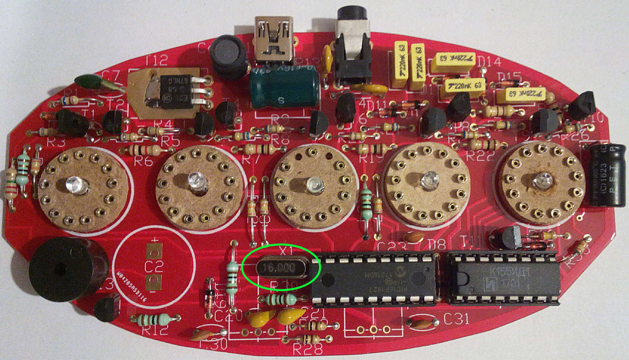
Fit the crystal marked 16.000 in the place marked for X1:
- Mon Dec 17, 2018 8:13 pm
- Forum: Assembly Instructions for the IN-14 5-tube clock
- Topic: 2- BUTTON version PCB assembly - Bag2
- Replies: 7
- Views: 17842
Re: BUTTON version PCB assembly - Bag2
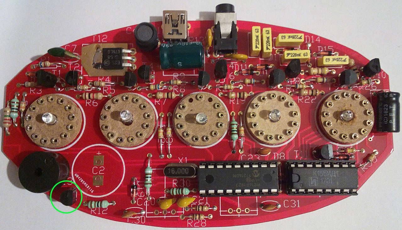
Now fit T13 (2N7000) - it looks the same as T1-11 so was packed in the second bag to avoid it being mixed up. The flat edge faces RIGHT.
- Mon Dec 17, 2018 8:12 pm
- Forum: Assembly Instructions for the IN-14 5-tube clock
- Topic: 2- BUTTON version PCB assembly - Bag2
- Replies: 7
- Views: 17842
Re: BUTTON version PCB assembly - Bag2
Fit T12 (the square black plastic 3 legged part), bending the end 3mm of its legs down 90 degrees to fit in the holes. Make sure it lies flat on the PCB and solder the tab on the top first, then the three legs. Some kits may be supplied with a version only having 2 legs - don't worry as the tab prov...
- Mon Dec 17, 2018 7:58 pm
- Forum: Assembly Instructions for the IN-14 5-tube clock
- Topic: 1- BUTTON version PCB assembly - Bag1
- Replies: 20
- Views: 38293
Re: BUTTON version PCB assembly - Bag1
Fit the 2x 22pF yellow ceramic capacitors marked '220' in C20,21: http://www.lasermad.com/instructions/IN14%20BUTTON/in14buttonpcbX.jpg Time to start on Bag 2, but first take a few minutes to go back through the instructions and double-check you've got eveything in the right place. Correcting mistak...