Search found 923 matches
- Sat Sep 15, 2012 11:23 pm
- Forum: Assembly instructions
- Topic: Board PCB
- Replies: 14
- Views: 57991
Re: Board PCB
Take 3 5V1 zener diodes from the component pile: http://www.lasermad.com/instructions/DSCF5208%205v1.jpg Fit them in the locations marked here: These are polarised, make sure the band is facing in the same direction as shown. http://www.lasermad.com/instructions/DSCF52195v1.jpg http://www.lasermad.c...
- Sat Sep 15, 2012 11:21 pm
- Forum: Assembly instructions
- Topic: Board PCB
- Replies: 14
- Views: 57991
Re: Board PCB
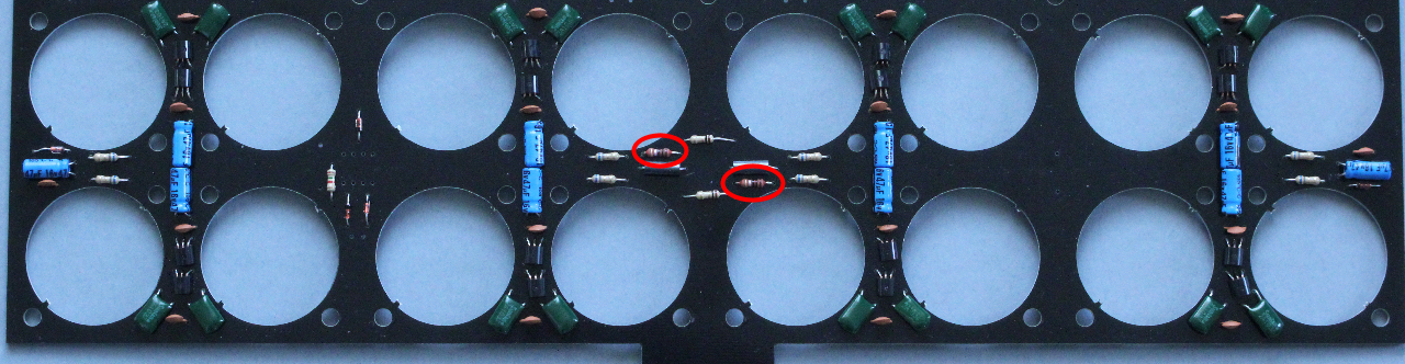
Take 1 1K5 resistor from the component pile:
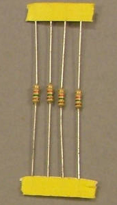
Fit it in the location marked here:

Solder in place etc....
Fit it in the location marked here:
Solder in place etc....
- Sat Sep 15, 2012 11:18 pm
- Forum: Assembly instructions
- Topic: Board PCB
- Replies: 14
- Views: 57991
Re: Board PCB
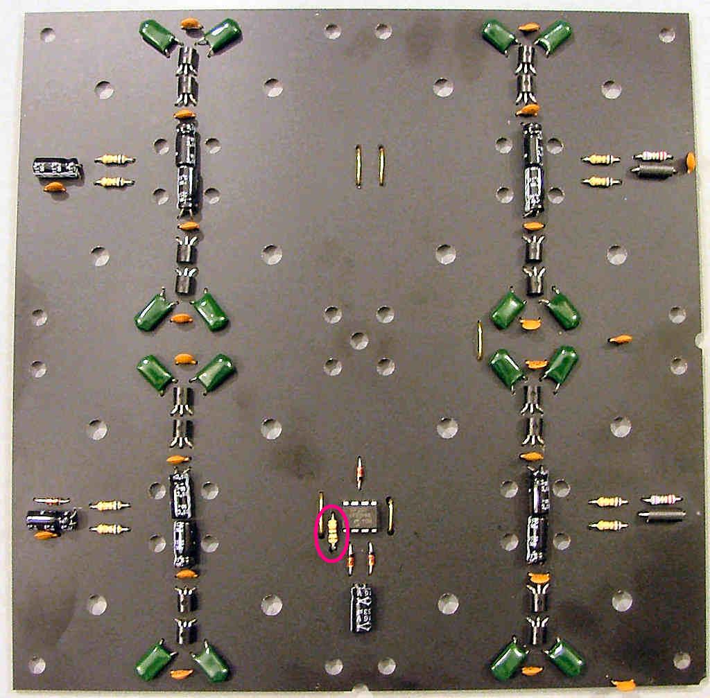
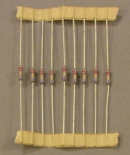
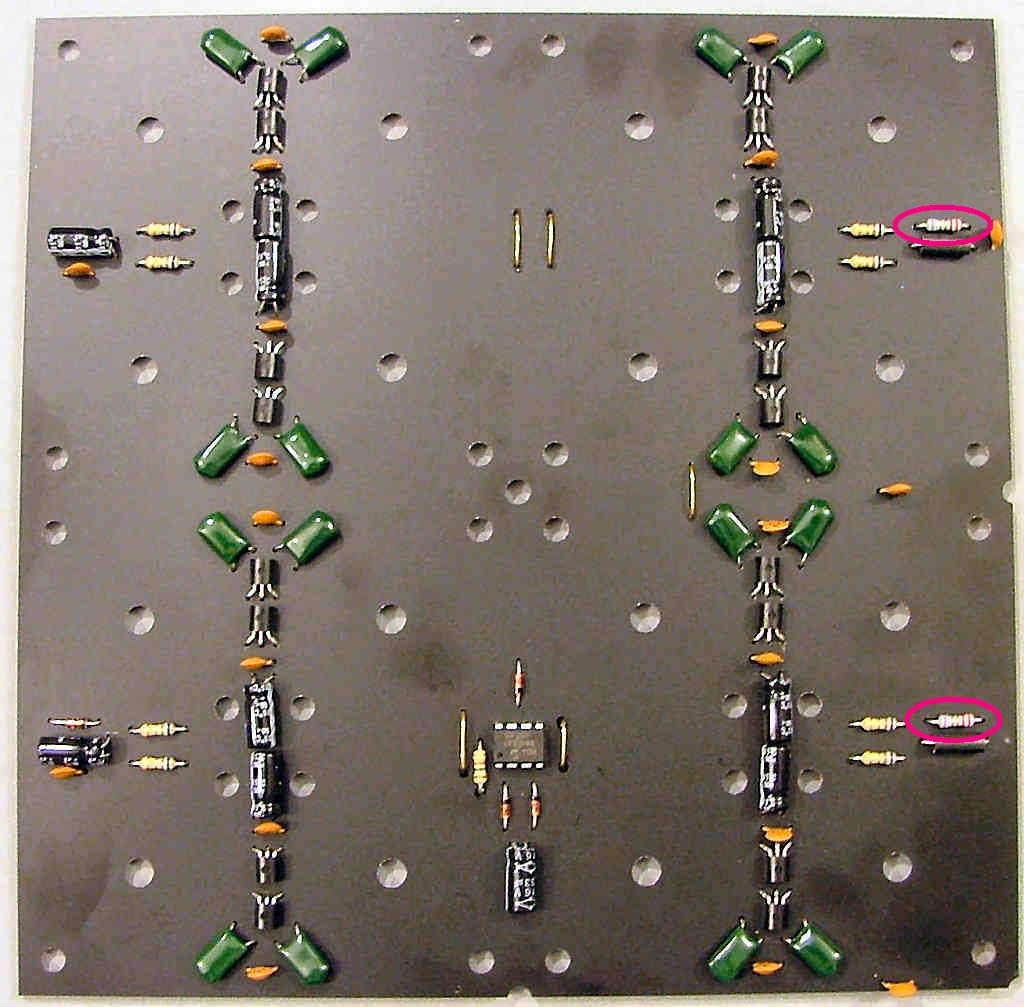
Take 2 2R2 resistors from the component pile:
Fit them in the locations marked here:
Solder in place etc....
Fit them in the locations marked here:
Solder in place etc....
- Sat Sep 15, 2012 11:16 pm
- Forum: Assembly instructions
- Topic: Board PCB
- Replies: 14
- Views: 57991
Re: Board PCB
I recommend leaving the partly built board until last, if you run into problems you'll then have at least one working board to make comparisons with. Clean one of the PCBs using a polish block or emery paper as you did with the display PCBs then check for any copper whiskers. Take 2 Ferrite links fr...
- Sat Sep 15, 2012 10:47 pm
- Forum: Nixie Chessboard V1
- Topic: Permissions/Bugs
- Replies: 11
- Views: 56127
Re: Permissions/Bugs
One day I'll finally get all the permissions to sit down and behave... I checked that one a few times, now find it was set to undefined.
It's just for discussion about a possible future version that I thought would be easier there than by email.
It's just for discussion about a possible future version that I thought would be easier there than by email.
- Sat Sep 15, 2012 10:39 pm
- Forum: Assembly instructions
- Topic: Powering up the complete parts
- Replies: 35
- Views: 111930
Powering up the complete parts
NOTE: This information only applies to the first 20 kits supplied with plain copper engraved PCBs not the later etched boards and is left here for those who may not yet have started on the old kits. -----------------------------------------------------------------------------------------------------...
- Sat Sep 15, 2012 10:25 pm
- Forum: Assembly instructions
- Topic: Board PCB
- Replies: 14
- Views: 57991
Board PCB
For this you will need the entire contents of BAG 5 and the 4 base PCBs: Unpack and sort out the components into seperate piles: Clockwise from top LH corner: 34x 6R8 resistors 9x 2R2 resistors 4x 1K5 resistors 30g solder 3x PIC10F200 microcontrollers 9x 14V zener diodes 11x 5V1 zener diodes. Be car...
- Sat Sep 15, 2012 4:37 pm
- Forum: Assembly instructions
- Topic: Piece display PCB discussion
- Replies: 61
- Views: 178691
Piece display PCB discussion
Suggestions for improvements, mistakes, hints here please.
- Sat Sep 15, 2012 4:30 pm
- Forum: Assembly instructions
- Topic: Piece display PCB
- Replies: 4
- Views: 25758
Re: Piece display PCB
Pin positions for various pieces: minion: 16x http://www.lasermad.com/instructions/DSCF5175m.jpg King (IN-7) and Knight (IN-7A): 6x http://www.lasermad.com/instructions/DSCF5175K.jpg Alfiere: 4x http://www.lasermad.com/instructions/DSCF5175A.jpg Vizier: 2x http://www.lasermad.com/instructions/DSCF5...
- Sat Sep 15, 2012 3:49 pm
- Forum: Assembly instructions
- Topic: Piece display PCB
- Replies: 4
- Views: 25758
Re: Piece display PCB
Display socket pins: Take one of the 15-pin 'D' sockets and cut open one rivet: http://www.lasermad.com/instructions/DSCF5164.jpg Open up the socket housing and remove the pins. http://www.lasermad.com/instructions/DSCF5188.jpg Cut the excess pin off just below the centre bulge. http://www.lasermad...