Page 1 of 1
2- BUTTON version PCB assembly - Bag2
Posted: Wed Dec 12, 2018 10:06 pm
by Tony
Fit the IC sockets SK3 and 4 as shown, making sure BOTH the notches face D8 as marked on the PCB. Do not fit the ICs for now:

Re: BUTTON version PCB assembly - Bag2
Posted: Mon Dec 17, 2018 8:12 pm
by Tony
Fit T12 (the square black plastic 3 legged part), bending the end 3mm of its legs down 90 degrees to fit in the holes. Make sure it lies flat on the PCB and solder the tab on the top first, then the three legs. Some kits may be supplied with a version only having 2 legs - don't worry as the tab provides the third connection.
DON'T FORGET TO SOLDER THE TAB! it acts as a heatsink connection to the PCB.

Re: BUTTON version PCB assembly - Bag2
Posted: Mon Dec 17, 2018 8:13 pm
by Tony
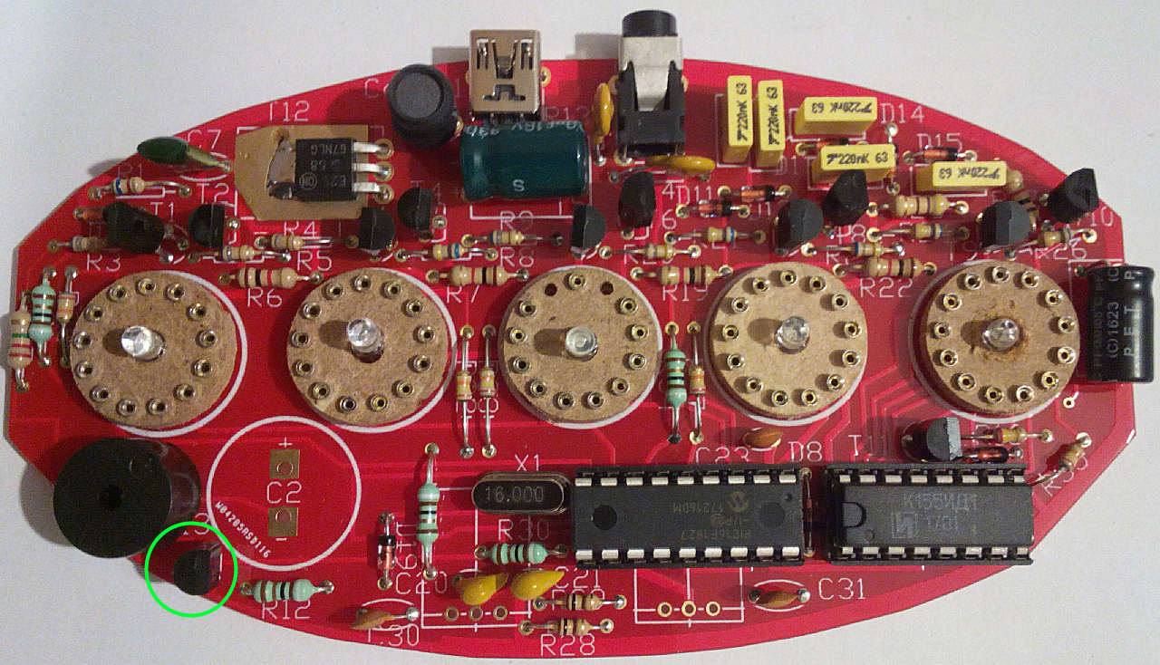
Now fit T13 (2N7000) - it looks the same as T1-11 so was packed in the second bag to avoid it being mixed up. The flat edge faces RIGHT.
Re: BUTTON version PCB assembly - Bag2
Posted: Mon Dec 17, 2018 8:15 pm
by Tony
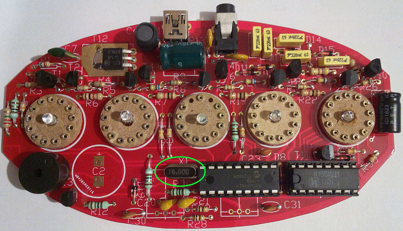
Fit the crystal marked 16.000 in the place marked for X1:
Re: BUTTON version PCB assembly - Bag2
Posted: Mon Dec 17, 2018 8:17 pm
by Tony
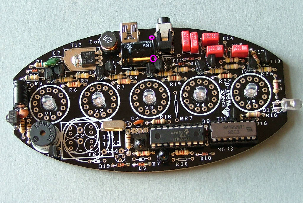
Now that is out of the way it's time to try power for the first time. Connect a multimeter on a current range (about 0-500mA) between the pads where R13 will be - this is just to the right of C8. Connect the + red lead to the topmost pad and the - black lead to the lower pad. Plug in the USB power supply and switch on.
You should have a reading of a few mA which rapidly drops to almost nothing as C8 charges. Switch off and disconnect everything. If the test was OK move onto the next stage, if not check for solder bridges. If there was no reading at all make sure your meter is working and connected correctly.
Re: BUTTON version PCB assembly - Bag2
Posted: Mon Dec 17, 2018 8:18 pm
by Tony
Fit IC1 (PIC 16F1827) and IC2 (K155ID1) into their sockets and reconnect the multimeter and USB supply. Make sure both notches point towards D8, IC1 is 'upside down' relative to IC2.
This time the current reading should be about 20-25mA and the 5 blue LEDs will light up, flickering slightly.
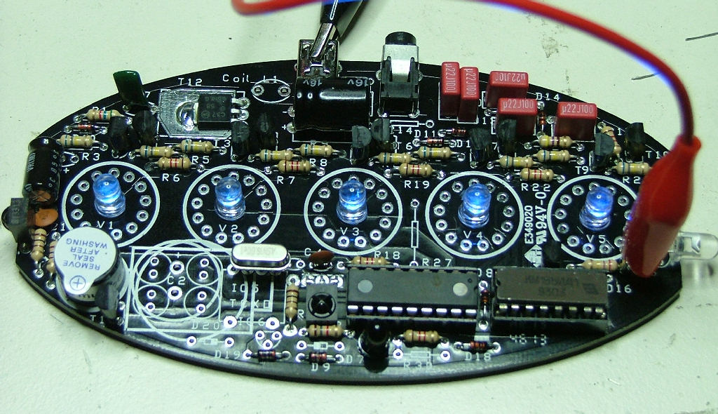
I cheated a little, it's being powered from a bench supply.
If it's reached this stage you now know the CPU is running and there are no major faults.
Re: BUTTON version PCB assembly - Bag2
Posted: Mon Dec 17, 2018 8:21 pm
by Tony
Fit the 2x 3-pin strips from bag1 in the locations marked here. These are used to connect the touchswitch modules to the main PCB:

Re: BUTTON version PCB assembly - Bag2
Posted: Mon Dec 17, 2018 8:23 pm
by Tony
Now carefully solder the switches onto the top of the pin strips. They'll need to be right at the top of them to be close to the case lid:

Power up the board again and test the switches. They have a red LED that should light up when your finger is near the sensor. Activate both switches for a couple of seconds and the buzzer should beep, indicating the clock is in menu mode.