PCB assembly

Instructions and discussion for constructors of our nixie button kit
Tony
Site Admin
Posts: 957
Joined: Tue Jul 24, 2012 8:05 pm

Re: PCB assembly

Post by Tony »

Temporarily connect the HV out wire to pin 11 of the nixie and power the board again, check the nixie glows when touched and the relay clicks (if you've removed that bridge across C6). Note that C1 takes about 30 seconds to recharge so the relay will only click if it hasn't been activated for at least that long. If you find it's not sensitive enough increase the value of R4 slightly (try 3k9), if the nixie isn't as bright as you would like try removing just one turn from L1.

If you do fry something it will probably be either T1 or L1, they're both available on ebay for example at $1-2 for 10 of each. If you want to alter the number of turns on L1 monitor the current and remember less (24-26) turns will produce more voltage but use more power. The output from L1 is safe as it is high frequency AC, as long as you don't add a rectifier diode and capacitor the only risk will be of small burns caused by touching the HV pin. Still, don't deliberately touch or misuse it.

Image

To produce the gowing ring effect make a loop of uninsulated wire around the nixie glass and connect it to ground.
Tony
Site Admin
Posts: 957
Joined: Tue Jul 24, 2012 8:05 pm

Re: PCB assembly

Post by Tony »

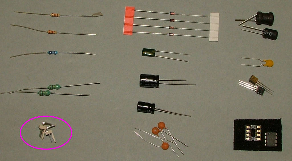
If you just intend to use the button as a plasma ball it can be powered by USB and the connectors SK2 and SK3 ignored. For switching or integrating into something larger though these are used to supply 5V without a bulky cable/connector and connect the 'NO' relay contacts to the outside world and connector pins and housings are supplied to make up suitable cables.

Note the relay is only intended to switch low voltage isolated loads and is not certified for connection to the mains supply.

A simple application example would be to connect the relay contacts to a motherboard 'PWR' input to switch a PC on/off using the nixie button.

Image
Post Reply