PCB assembly

Instructions and discussion for constructors of our nixie button kit
Tony
Site Admin
Posts: 957
Joined: Tue Jul 24, 2012 8:05 pm

PCB assembly

Post by Tony »

The exact order of assembly will depend on the preference of the builder but convention is to fit the resistors/diodes first followed by capacitors, transistors and finally the IC socket/USB/conectors in that order.

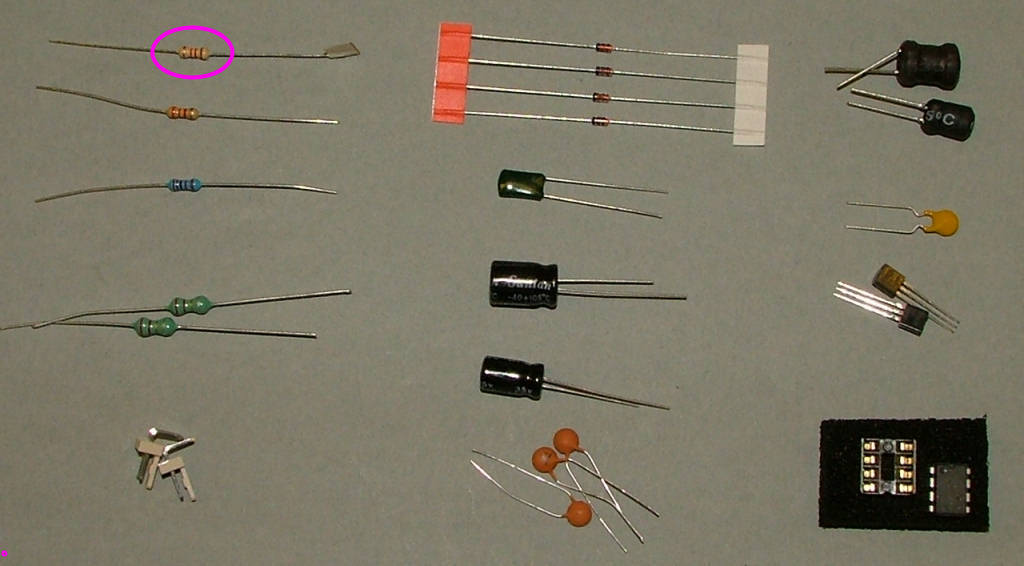
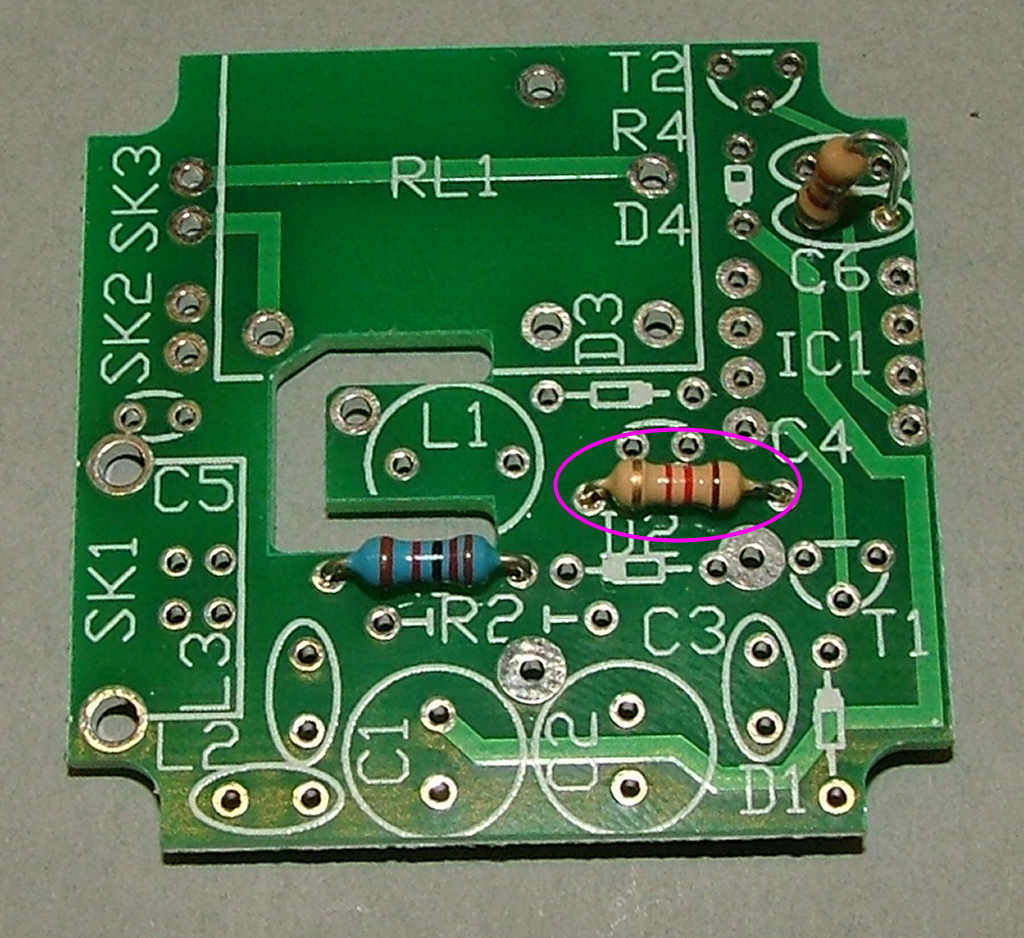
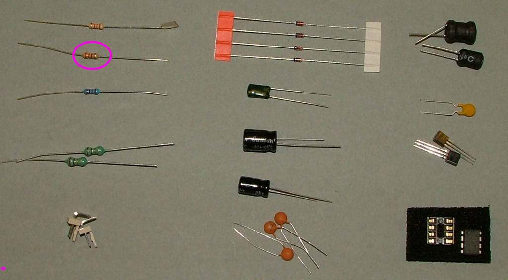
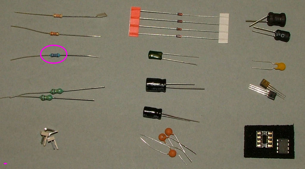
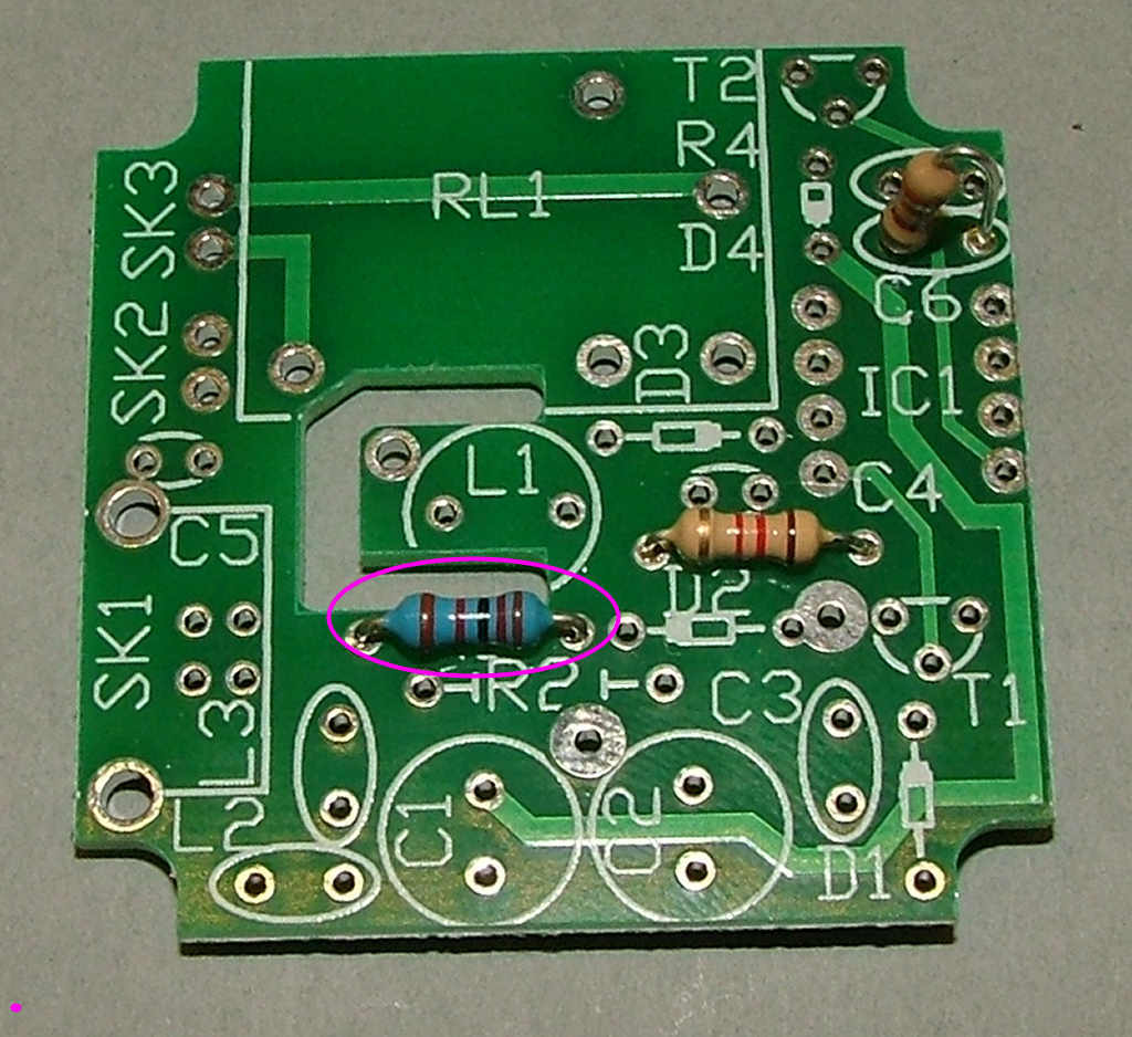
After preparing a suitable working space take the PCB and the 1K2 resistor (Brown Red Red) or 1k (brown black red). Fit this in the location marked for R3 as shown:

Image


Image
Tony
Site Admin
Posts: 957
Joined: Tue Jul 24, 2012 8:05 pm

Re: PCB assembly

Post by Tony »

Fit the 2k2 resistor (Red Red Red). Fit this in the location marked for R4 as shown:

Image


Image
Tony
Site Admin
Posts: 957
Joined: Tue Jul 24, 2012 8:05 pm

Re: PCB assembly

Post by Tony »

Fit the 12K resistor (Brown Red Black Brown). Fit this in the location marked for R1 as shown:

Image


Image
Tony
Site Admin
Posts: 957
Joined: Tue Jul 24, 2012 8:05 pm

Re: PCB assembly

Post by Tony »

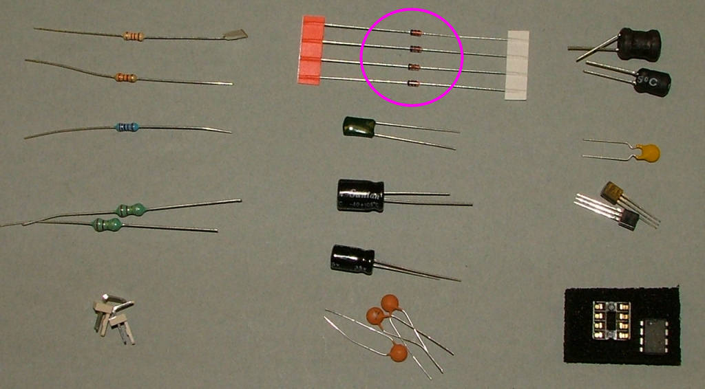
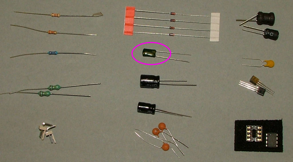
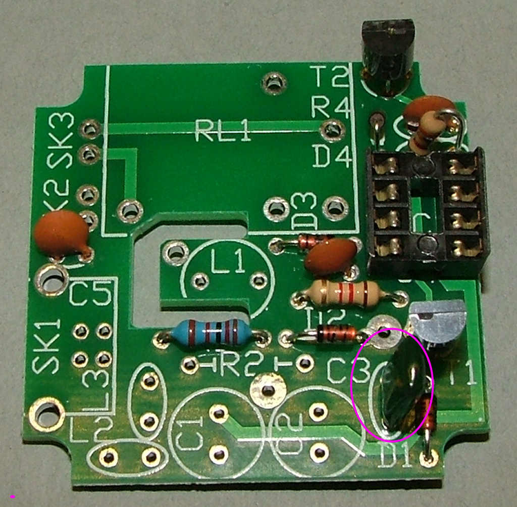
Now for the diodes (small glass beads). Fit these in the location marked for D1-4 as shown. Note they have to fitted the right way round, the black band faces the same way as the white band printed on the PCB under them:

Image


Image
Tony
Site Admin
Posts: 957
Joined: Tue Jul 24, 2012 8:05 pm

Re: PCB assembly

Post by Tony »

Next the 10n or 33n capacitors (brown discs). Fit these in the location marked for C4,5 and 6:

Image


Image
Tony
Site Admin
Posts: 957
Joined: Tue Jul 24, 2012 8:05 pm

Re: PCB assembly

Post by Tony »

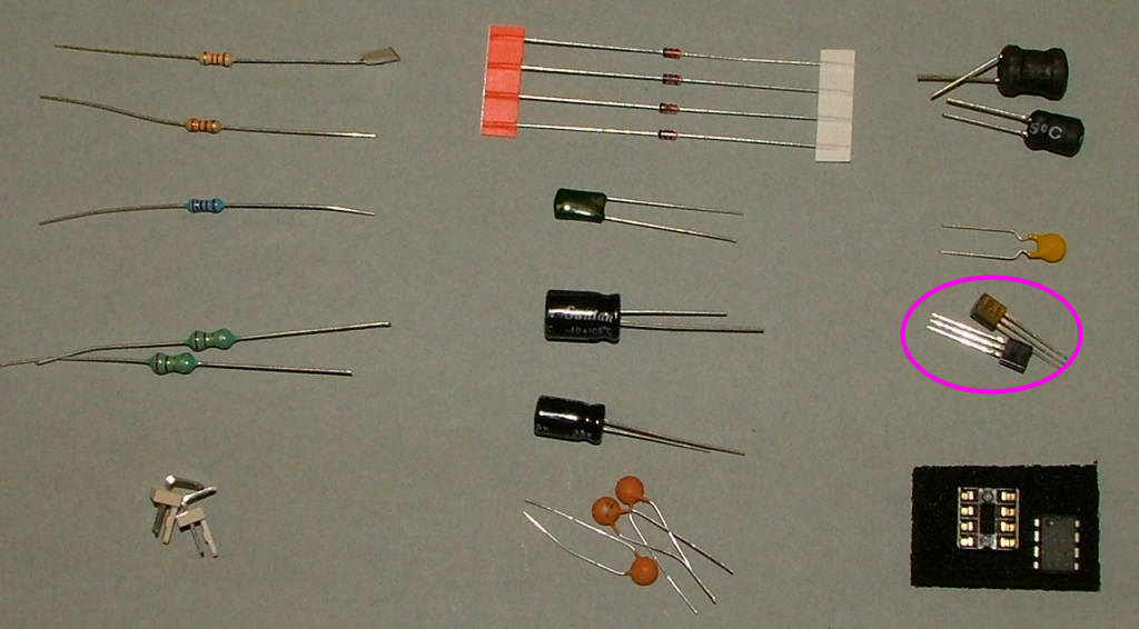
Now the transistors. Fit these in the location marked for T1 and T2 as shown. The flat side faces to the top of the board as shown and is also printed on the PCB:

Image


Image
Tony
Site Admin
Posts: 957
Joined: Tue Jul 24, 2012 8:05 pm

Re: PCB assembly

Post by Tony »

Fit the 4n7 mylar capacitor (green resin bead) in the location marked for C3:

Image


Image
Tony
Site Admin
Posts: 957
Joined: Tue Jul 24, 2012 8:05 pm

Re: PCB assembly

Post by Tony »

Fit the 8 pin IC socket in the location marked for IC1 as shown. The 'notch' in one side faces to the top:

Image


Image
Tony
Site Admin
Posts: 957
Joined: Tue Jul 24, 2012 8:05 pm

Re: PCB assembly

Post by Tony »

Solder the 2x 2 pin plugs or 90 degree headers (later kits) in the locations marked for SK2 and SK3 as shown:

Image


Image
Tony
Site Admin
Posts: 957
Joined: Tue Jul 24, 2012 8:05 pm

Re: PCB assembly

Post by Tony »

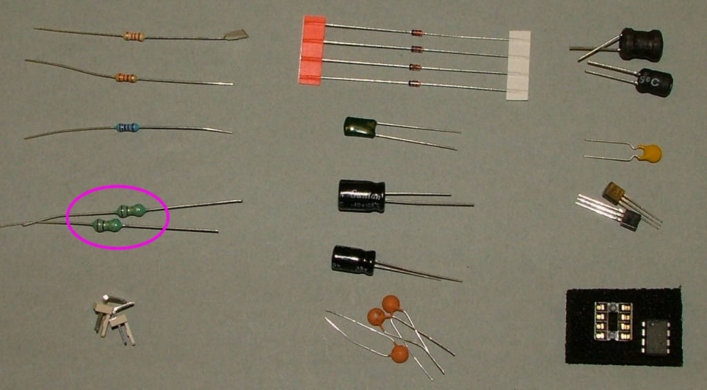
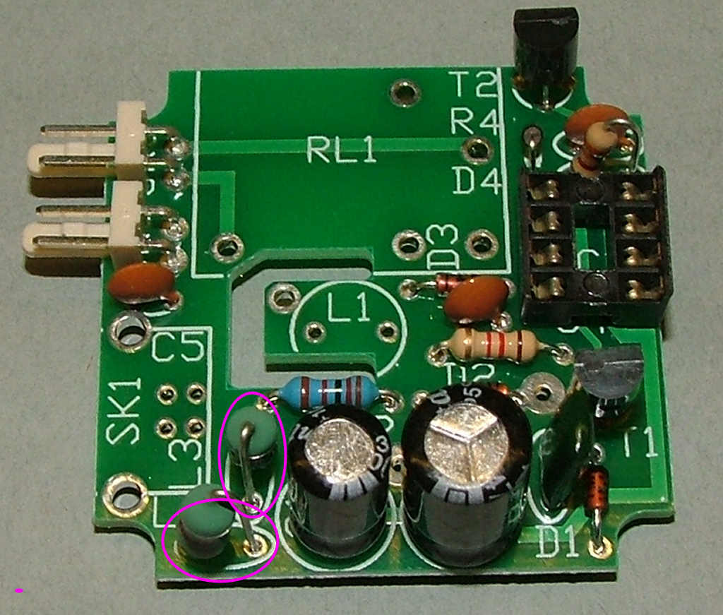
Next the two axial coils. These are only supplied with the first batch of kits, later versions do not include them - just replace with wire links. Fit these in the locations marked for L2, L3:

Image


Image
Post Reply