Case assembly

Instructions and discussion for constructors of our nixie button kit
Tony
Site Admin
Posts: 957
Joined: Tue Jul 24, 2012 8:05 pm

Case assembly

Post by Tony »

Bag2 (Bolts) and Bag3 (Case parts) are needed now, plus the assembled PCB and nixie.

After sanding and polishing (if required) the case parts start assembly by sticking the 4 feet from bag2 to the base piece as shown here:

Image
Tony
Site Admin
Posts: 957
Joined: Tue Jul 24, 2012 8:05 pm

Re: Case assembly

Post by Tony »

Push the 4 bolts through the base holes - don't use washers - and turn upright:

Image
Tony
Site Admin
Posts: 957
Joined: Tue Jul 24, 2012 8:05 pm

Re: Case assembly

Post by Tony »

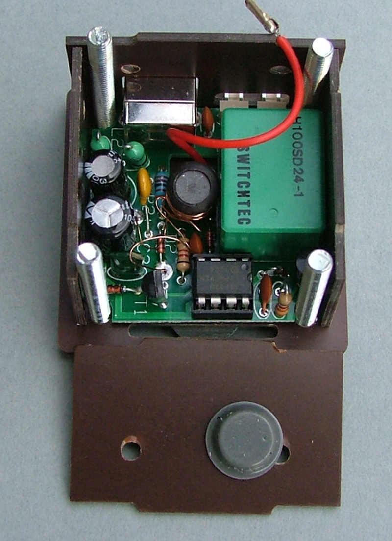
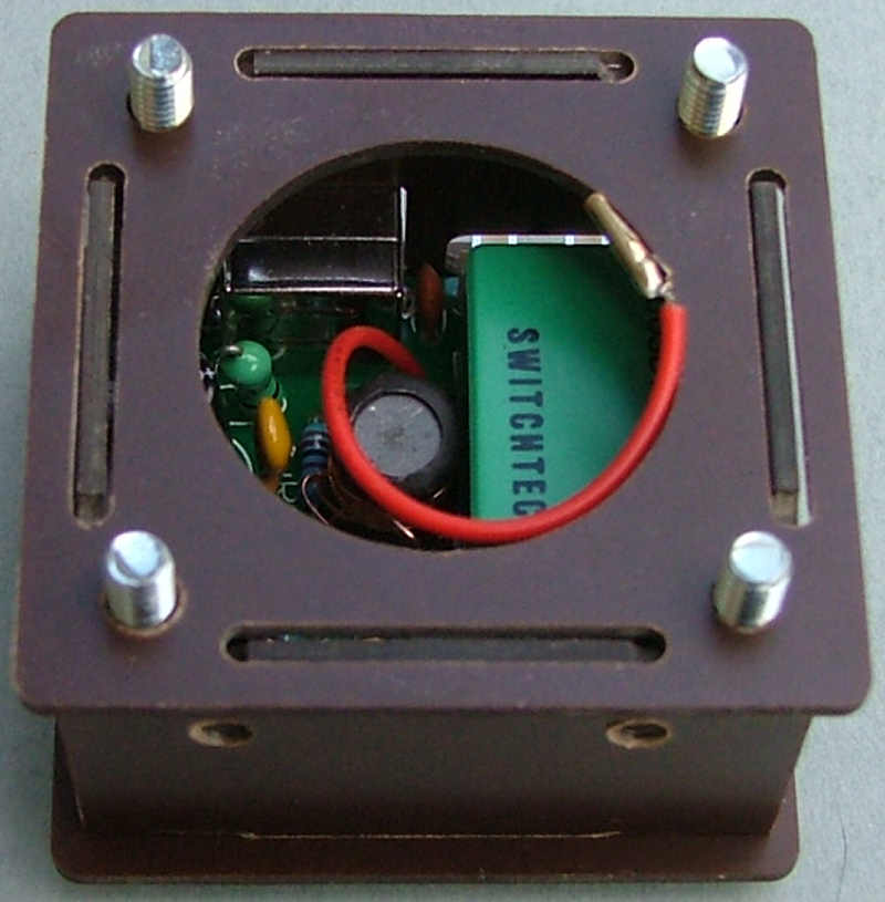
Drop the PCB and back panel in, you should find the sticky rubber feet help hold the side pieces in place a little. Check the 2-pin connectors at the back can be used with the power supply/relay connectors you have, you may need to enlarge the opening for some connector housings to fit through:

Image
Tony
Site Admin
Posts: 957
Joined: Tue Jul 24, 2012 8:05 pm

Re: Case assembly

Post by Tony »

Then the other 3 sides. Use one or both of the rubber feet from bag1 on the inside sides to hold the pcb in place:

Image
Tony
Site Admin
Posts: 957
Joined: Tue Jul 24, 2012 8:05 pm

Re: Case assembly

Post by Tony »

Drop the top panel on, the side pieces will be held in place by the notches:

Image
Tony
Site Admin
Posts: 957
Joined: Tue Jul 24, 2012 8:05 pm

Re: Case assembly

Post by Tony »

Finally the lid covers the notches, use the 4 washers on top:

Image

And hold it together with the dome nuts:

Image
Tony
Site Admin
Posts: 957
Joined: Tue Jul 24, 2012 8:05 pm

Re: Case assembly

Post by Tony »

Trim the HV wire to the shortest length that will allow you to still attach it to the nixie and solder it to pin 11.

Push it into the case, it should be tight enough to be held in place but still fit flush with the top panel.

Image
Post Reply