Page 2 of 3
Re: PCB assembly - BAG1
Posted: Mon Sep 07, 2015 2:33 am
by Tony
Fit the yellow plastic .22u capacitors x5 in locations marked for C9,10,11,12 and 13 as shown:

Re: PCB assembly - BAG1
Posted: Mon Sep 07, 2015 2:37 am
by Tony
Next you'll need to assemble the paxolin sockets for the nixies. Red PCB - they're made from MDF, it's much easier to push the pins into these.
NOTE that from 2021- many kits will be supplied without the sockets due to some constructors becoming frustrated trying to get nixie leads into them. In this case, skip this step for now until the rest of the PCB is completed.
Using wirecutters or pliers carefully break the turned pin sockets out of the plastic housing:

Push the pins into the bakelite holder:

Once made, drop them into the V1-5 positions on the PCB and solder them in place.
Re: PCB assembly - BAG1
Posted: Mon Sep 07, 2015 2:38 am
by Tony
Fit the black plastic transistors x5 marked 'MPSA92' or '2N6520**' in locations marked for T1,3,5,7 and 9 as shown: NOTE these are polarised and must be fitted the right way round. There is a flat mark on one side of the body, this flat side faces to the LEFT of the PCB when viewed as shown in the photograph.

Re: PCB assembly - BAG1
Posted: Mon Sep 07, 2015 2:40 am
by Tony
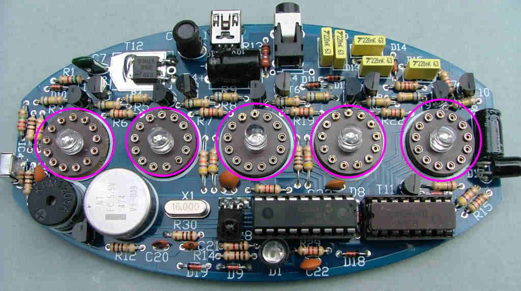
Now fit the LEDs through the centre hole so they sit on
top of the socket. NOTE that these are polarised and must be fitted the right way round.
The SHORT PIN faces to the LEFT of the PCB when viewed from the front.

Re: PCB assembly - BAG1
Posted: Mon Sep 07, 2015 2:43 am
by Tony
Fit the black plastic transistors marked 'MPSA42' or 'KSP42' in locations marked for T2,4,6,8,10 and 11 as shown: NOTE these are polarised and must be fitted the right way round. There is a flat mark on one side of the body, this flat side faces to the RIGHT of the PCB when viewed as shown in the photograph.

Re: PCB assembly - BAG1
Posted: Mon Sep 07, 2015 2:44 am
by Tony
Fit the green resin 4n7 capacitor in the location marked for C7 as shown:

Re: PCB assembly - BAG1
Posted: Mon Sep 07, 2015 2:45 am
by Tony
Fit the aluminium can 2.2/3.3u 200/250V capacitor in the location marked for C6 as shown - the white bar on the side of the capacitor indicated the negative- terminal and faces to the right:

Re: PCB assembly - BAG1
Posted: Mon Sep 07, 2015 2:46 am
by Tony
Fit the green or black aluminium can 330u/470u 10V/16V capacitor in the location marked for C8 as shown: NOTE this is polarised, the negative- terminal is marked with a white band. This faces towards the BACK/TOP of the PCB when viewed as shown.

Re: PCB assembly - BAG1
Posted: Mon Sep 07, 2015 2:48 am
by Tony
Carefully fit the USB socket, it may be a little tight but don't push too much or you may damage the pins. Fit the 3.5mm jack socket marked SK2:
***If you received a socket with 5 pins remove the 'tail' at the centre back of the socket.


Re: PCB assembly - BAG1
Posted: Mon Sep 07, 2015 2:50 am
by Tony
Fit the brown disc 22pF or 27pF capacitors in the locations marked for C20 and 21 as shown:
*** May be square beige resin 22pF, you'll need to bend the pins a bit to fit on these.
