1- IR version PCB Assembly - Bag1

Tony
Site Admin
Posts: 949
Joined: Tue Jul 24, 2012 8:05 pm

1- IR version PCB Assembly - Bag1

Post by Tony »

First of all I should mention there are now 2 versions, one using the IR proximity sensor and one using two touchswitches for control. If you have a Bag1 labelled 'CLK501B' and your Bag2 contains 2 small red PCBs then you have the touchswitch version. They are almost identical but to avoid confusion it has its' own assembly threads prefixed 'BUTTON'. Please follow those rather than this one.

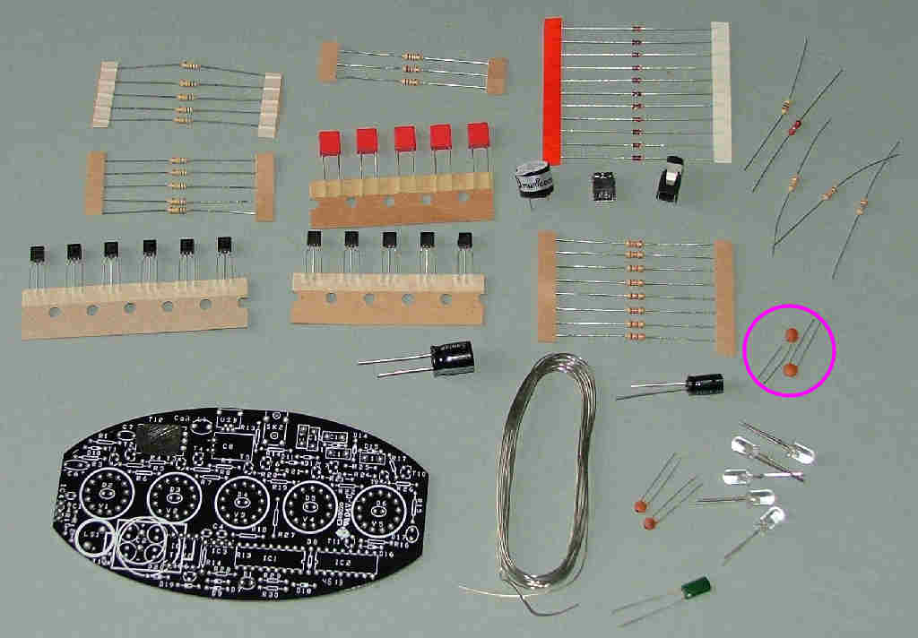
The exact order of assembly will depend on the preference of the builder but convention is to fit the resistors/diodes first followed by capacitors, transistors and ICs in that order.

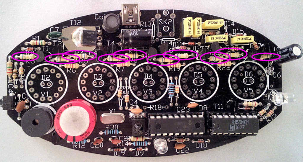
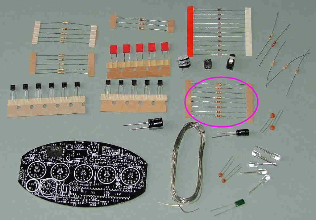
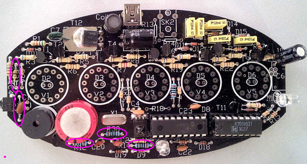
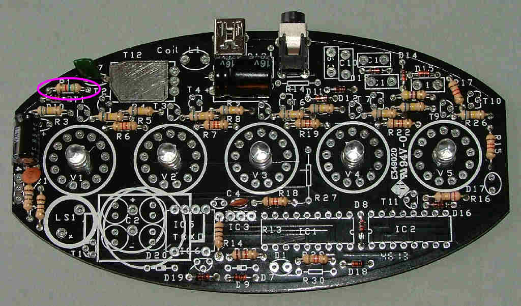
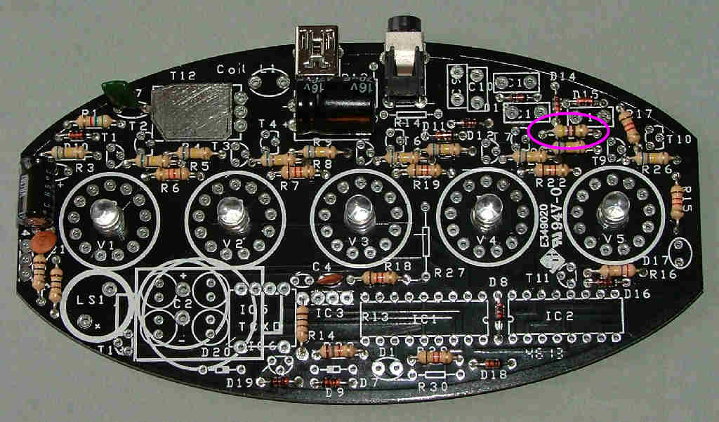
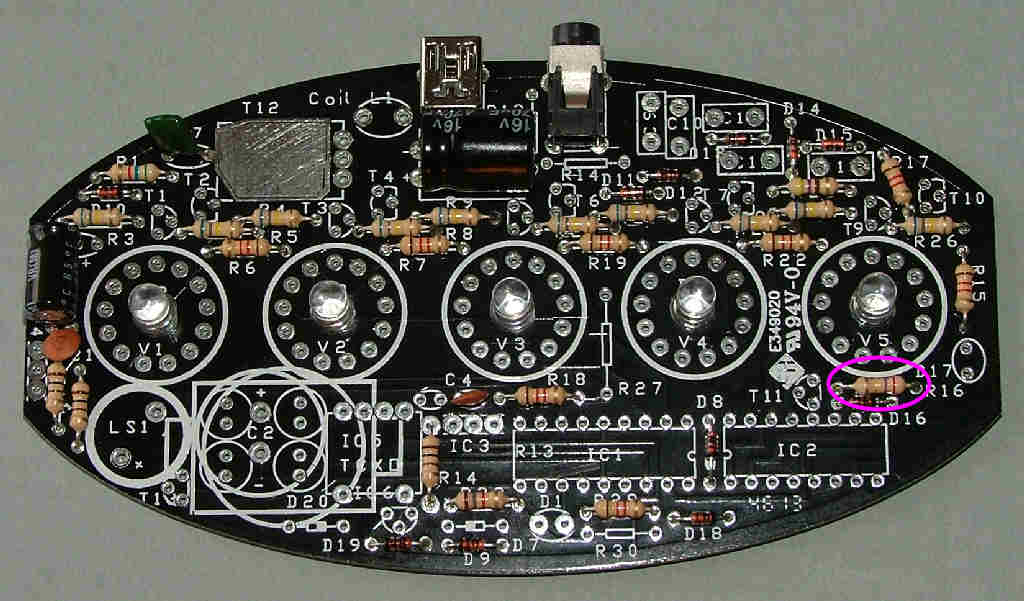
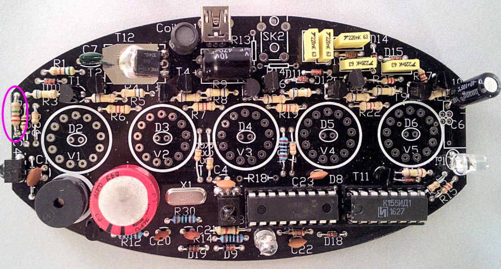
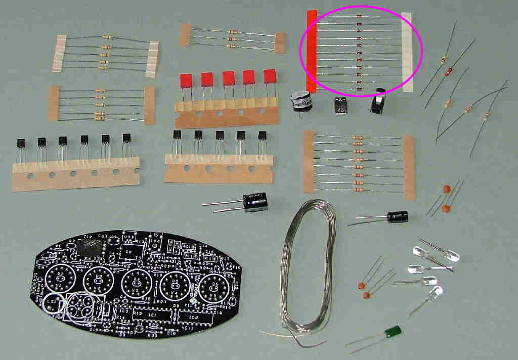
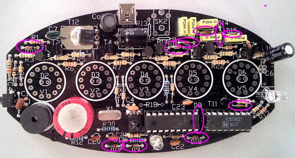
After preparing a suitable working space take the PCB and start with resistors R3,4,5,8,9,20,21,23,24 and 26. Over the years these have been 680k, (blue-grey-yellow) 560k (green blue yellow) and finally in the latest batch 2m2 (red red green). Fit these in locations marked for R3,4,5,8,9,20,21,23,24 and 26 as shown:

Image

Image
Tony
Site Admin
Posts: 949
Joined: Tue Jul 24, 2012 8:05 pm

Re: PCB Assembly - Bag1

Post by Tony »

Image

Fit the 9x 1K or 1K2 resistors (brown black red) or (brown-red-red) in locations marked for R6,7,15,17,18,19,22,25 and 29 as shown (note R18 is fitted though not shown here):

Image
Tony
Site Admin
Posts: 949
Joined: Tue Jul 24, 2012 8:05 pm

Re: PCB Assembly - Bag1

Post by Tony »

Image

Fit the 5x 100r resistors (brown-black-brown or brown-black-black-black) or 5x 91r resistors (white brown black) in locations marked for R11,12,14,31 and 30 as shown:

Image
Tony
Site Admin
Posts: 949
Joined: Tue Jul 24, 2012 8:05 pm

Re: PCB Assembly - Bag1

Post by Tony »

Fit the 5K6 resistor (green-blue-red) in the location marked for R1 as shown:

Image
Tony
Site Admin
Posts: 949
Joined: Tue Jul 24, 2012 8:05 pm

Re: PCB Assembly - Bag1

Post by Tony »

Fit the 470r resistor (yellow-purple-brown) in the location marked for R25 as shown:

Image
Tony
Site Admin
Posts: 949
Joined: Tue Jul 24, 2012 8:05 pm

Re: PCB Assembly - Bag1

Post by Tony »

Fit the 270k resistor (red-purple-yellow) in the location marked for R16 as shown

Image

Fit the 2M2 resistor (red-red-green) in the location marked for R37 as shown:

Image
Tony
Site Admin
Posts: 949
Joined: Tue Jul 24, 2012 8:05 pm

Re: PCB Assembly - Bag1

Post by Tony »

Fit the 1k8 resistor (brown-grey-red) in the location marked for R28 as shown:

Image
Tony
Site Admin
Posts: 949
Joined: Tue Jul 24, 2012 8:05 pm

Re: PCB Assembly - Bag1

Post by Tony »

Fit the 11x 1N4148 diodes in locations marked for D8,9,10,11,12,13,14,15,16,18,19 as shown: **NOTE** the band marked on the end of the diode body must face the same way as shown in the photograph, this is also indicated on the PCB with a thick white band.

Image

Image
Tony
Site Admin
Posts: 949
Joined: Tue Jul 24, 2012 8:05 pm

Re: PCB Assembly - Bag1

Post by Tony »

Image

Fit the brown 10n (marked 103) or 33n (marked 333) ceramic capacitors x3 in locations marked for C1,4 and 22 as shown - DO NOT fit one in C23 as in the picture - please ignore that component.

Image
Tony
Site Admin
Posts: 949
Joined: Tue Jul 24, 2012 8:05 pm

Re: PCB Assembly - Bag1

Post by Tony »

Fit the red or yellow plastic .22u capacitors x5 in locations marked for C9,10,11,12 and 13 as shown:

Image

Image

CONTINUED ON PAGE 2
Locked