Page 1 of 1
2 - Nixie PCB assembly
Posted: Thu Oct 15, 2015 4:23 pm
by Tony
The exact order of assembly will depend on the preference of the builder but convention is to fit the resistors/diodes first followed by capacitors, transistors and ICs in that order.
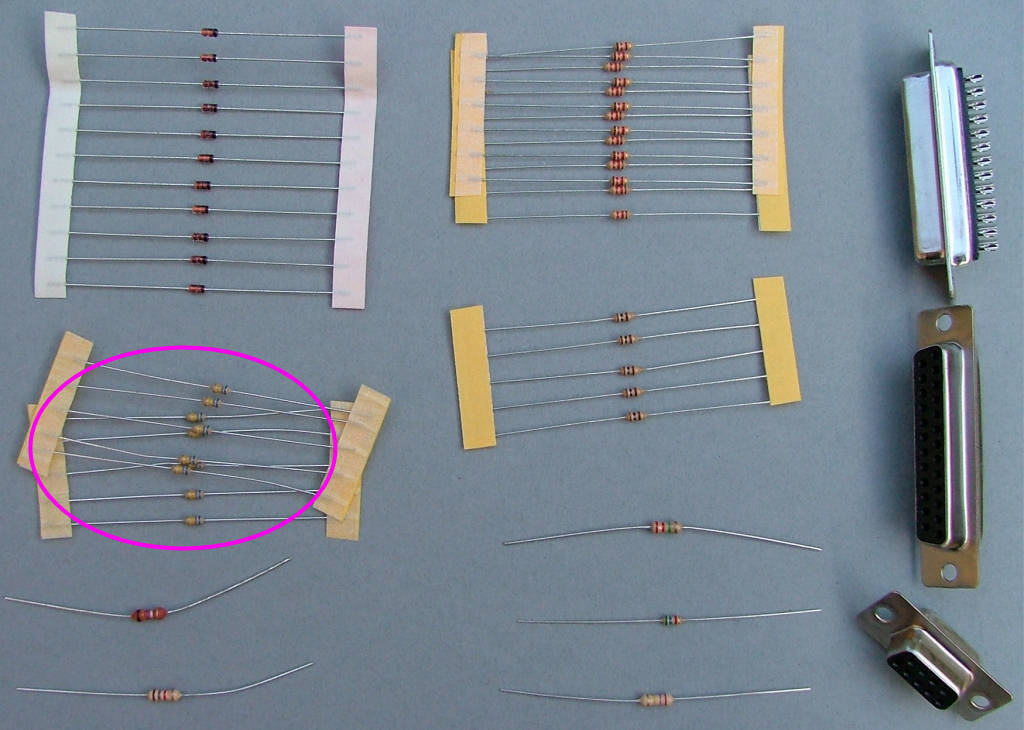
After preparing a suitable working space take the PCB and the 10x 680K resistors (blue-grey-yellow) or 2m2 (red red green). Fit these in locations marked for R24,25,26,27,28,29,30,31,32 and 34 as shown:
Re: Nixie PCB assembly
Posted: Mon Oct 19, 2015 2:39 am
by Tony
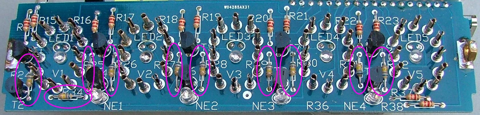
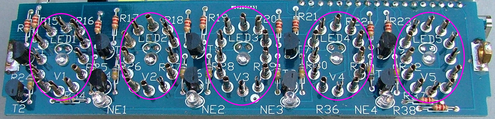
Fit the 12x 1K2 resistors (brown-red-red) or 1k (brown-black-red) in locations marked for R14,15,16,17,18,19,20,21,22,23,37 and 38 as shown:

Re: Nixie PCB assembly
Posted: Mon Oct 19, 2015 2:42 am
by Tony
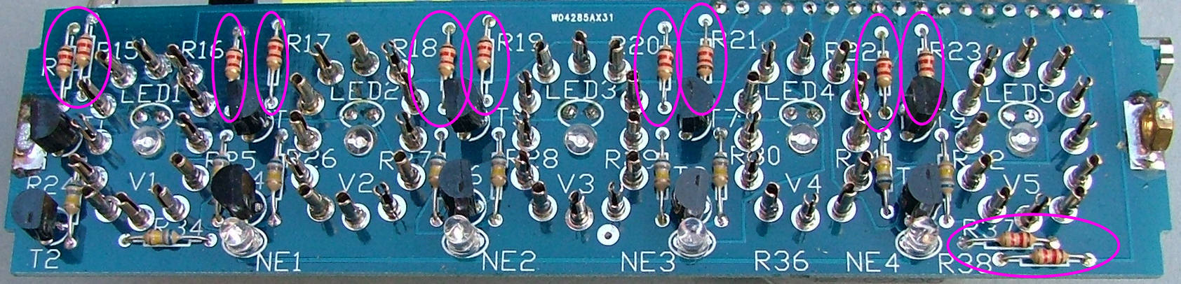
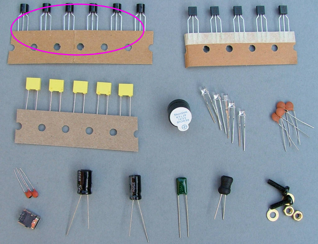
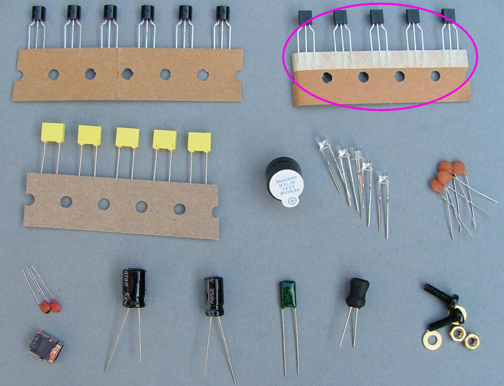
Fit 5 of the black plastic transistors marked 'MPSA42' or 'KSP42' in locations marked for T1,3,5,7 and 9 as shown: NOTE these are polarised and must be fitted the right way round. There is a flat mark on one side of the body, this flat side faces to the LEFT of the PCB when viewed as shown in the photograph.
Re: Nixie PCB assembly
Posted: Mon Oct 19, 2015 2:44 am
by Tony
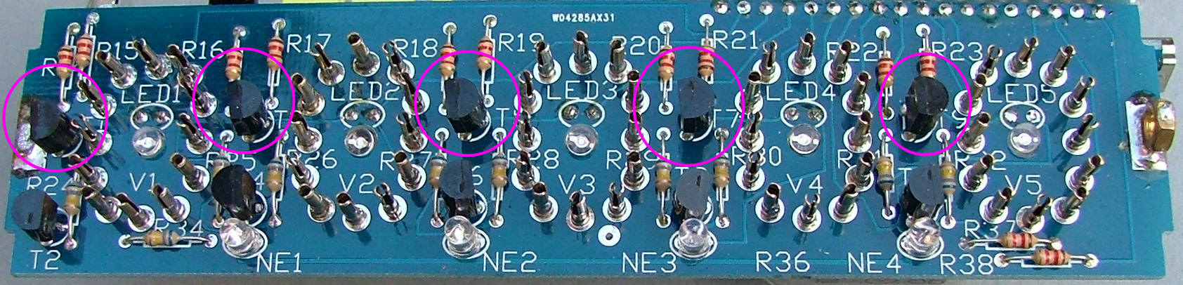
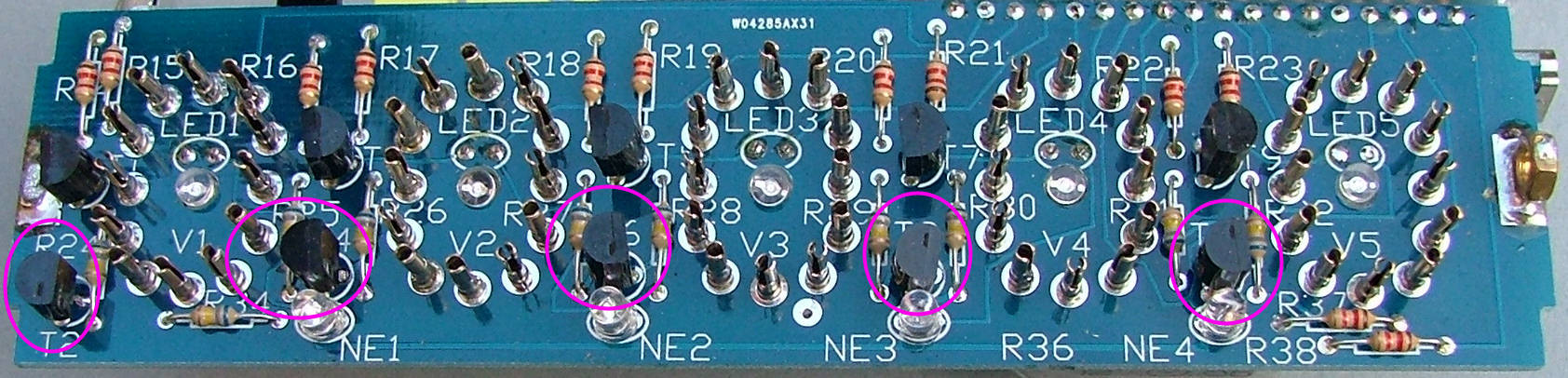
Fit the black plastic transistors x5 marked 'MPSA92', 'A92', 'KSP92' in locations marked for T2,4,6,8 and 10 as shown: NOTE these are polarised and must be fitted the right way round. There is a flat mark on one side of the body, this flat side faces to the RIGHT of the PCB when viewed as shown in the photograph.
Re: Nixie PCB assembly
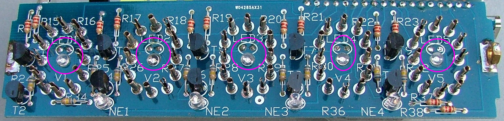
Posted: Mon Oct 19, 2015 2:48 am
by Tony
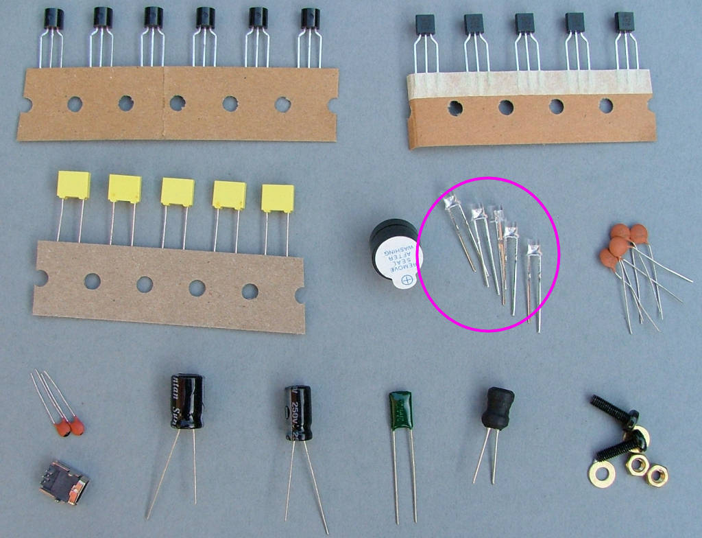
Now a tricky one: The 3mm blue backlight LEDs are fitted from behind the PCB through the holes under each nixie but with the wires running through to the top and are soldered from above. Bend the wires 180 degrees so the point up with the SHORT wire on the top left and the LONG wire on the top right when fitted through the PCB. These go in the places marked for LED 1,2,3,4 and 5.
Re: Nixie PCB assembly
Posted: Mon Oct 19, 2015 2:51 am
by Tony
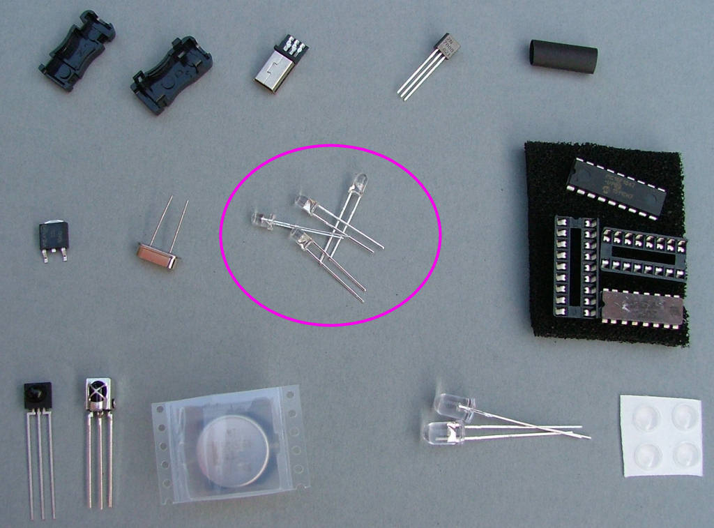
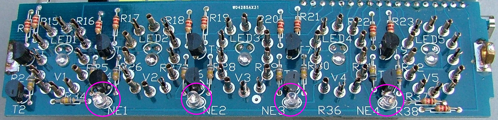
Next are the 4 amber decimal point LEDs. These originally used neons but I found LEDs to be more stable. You'll find them in bag 2 to prevent them being mixed up with the blue LEDs. If you received two 5mm IR LEDs, the amber LEDs will be water clear as in the pictures. If you received two 3mm IR LEDs, the amber LEDs have shorter wires. These again are polarised and the SHORT wire faces to the LEFT.
Re: Nixie PCB assembly
Posted: Mon Oct 19, 2015 2:53 am
by Tony
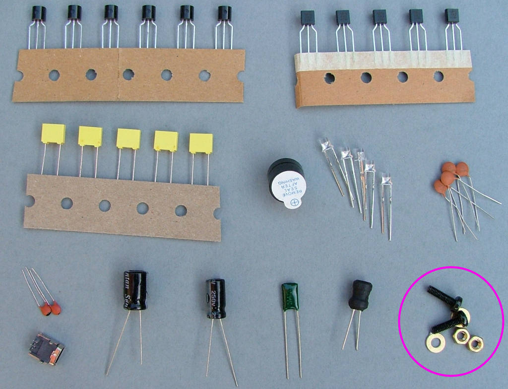
Solder the brass 3mm nuts to the PCB at each end, these hold the end caps in place when the case is assembled. Clean the brass and tin them first, they must have a good hold on the PCB.
Re: Nixie PCB assembly
Posted: Mon Oct 19, 2015 2:56 am
by Tony
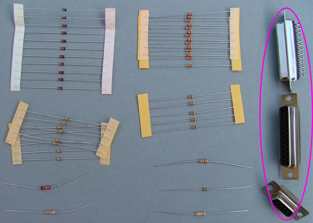
Finally you'll need to dismantle the 'D' sockets, remove the pins and solder them into the large holes indicated to form the nixie sockets.
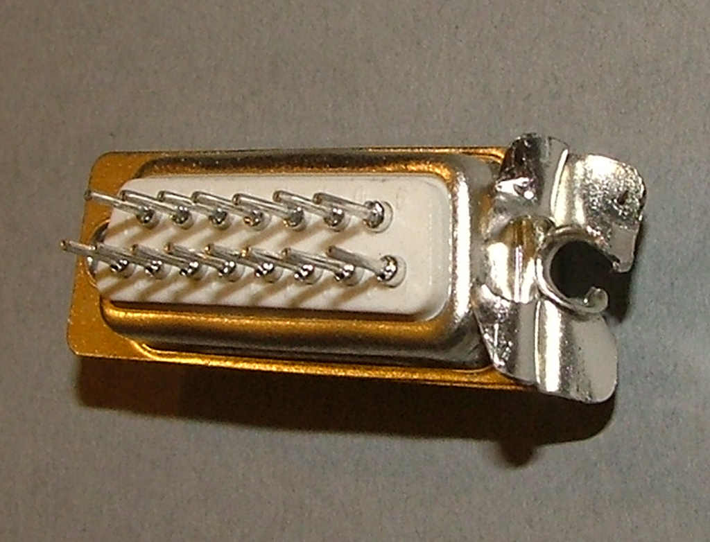
 Take one of the 'D' sockets and cut open one rivet:
 Open up the socket housing and remove the pins.
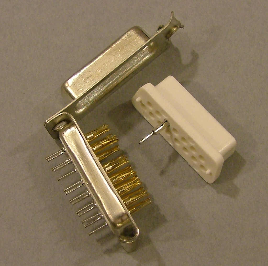
Note that only 11 pins are neede for each tube not 12, the bottom centre pin can be left out as it's only used as the DP connector in the IN-12b version of these tubes.
You'll probably find it easiest to fit all 11 pins to one socket then use one of the nixies to gently hold them in place whilst you solder them. That will ensure the pins are correctly aligned.
Re: Nixie PCB assembly
Posted: Mon Oct 19, 2015 3:00 am
by Tony
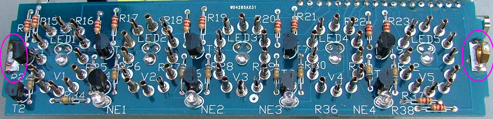
That's the display PCB completed, make sure all the component wires have been trimmed and there are no 'tails' or bridges then start on the controller PCB.