3 - Clock PCB assembly

Tony
Site Admin
Posts: 949
Joined: Tue Jul 24, 2012 8:05 pm

Re: Clock PCB assembly

Post by Tony »

Fit the mustard/beige resin dipped 22p (marked 220) or 33p (33) capacitors x2 in locations marked for C7 and C8:

Image

Image
Tony
Site Admin
Posts: 949
Joined: Tue Jul 24, 2012 8:05 pm

Re: Clock PCB assembly

Post by Tony »

Fit the aluminium can 2.2u 200/250V capacitor in the location marked for C10 as shown - the white bar on the side of the capacitor indicates the negative- terminal and faces to the TOP:

Image

Image
Tony
Site Admin
Posts: 949
Joined: Tue Jul 24, 2012 8:05 pm

Re: Clock PCB assembly

Post by Tony »

Fit the green or black aluminium can 470u or 330u capacitor in the location marked for C5 as shown: NOTE this is polarised, the negative- terminal is marked with a white band.

Image

Image
Tony
Site Admin
Posts: 949
Joined: Tue Jul 24, 2012 8:05 pm

Re: Clock PCB assembly

Post by Tony »

Fit the green resin 4n7 capacitor in the location marked for C3 as shown:

Image

Image
Tony
Site Admin
Posts: 949
Joined: Tue Jul 24, 2012 8:05 pm

Re: Clock PCB assembly

Post by Tony »

Fit the remaining black plastic transistor marked 'MPSA42' 'A42' or 'KSP42' in the location marked for T11 as shown: NOTE this are polarised and must be fitted the right way round. There is a flat mark on one side of the body, this flat side faces to the RIGHT of the PCB when viewed as shown in the photograph.

Image

Image
Tony
Site Admin
Posts: 949
Joined: Tue Jul 24, 2012 8:05 pm

Re: Clock PCB assembly

Post by Tony »

That's BAG1 finished for now, next fit the IC sockets from BAG2:

Image

Image
Tony
Site Admin
Posts: 949
Joined: Tue Jul 24, 2012 8:05 pm

Re: Clock PCB assembly

Post by Tony »

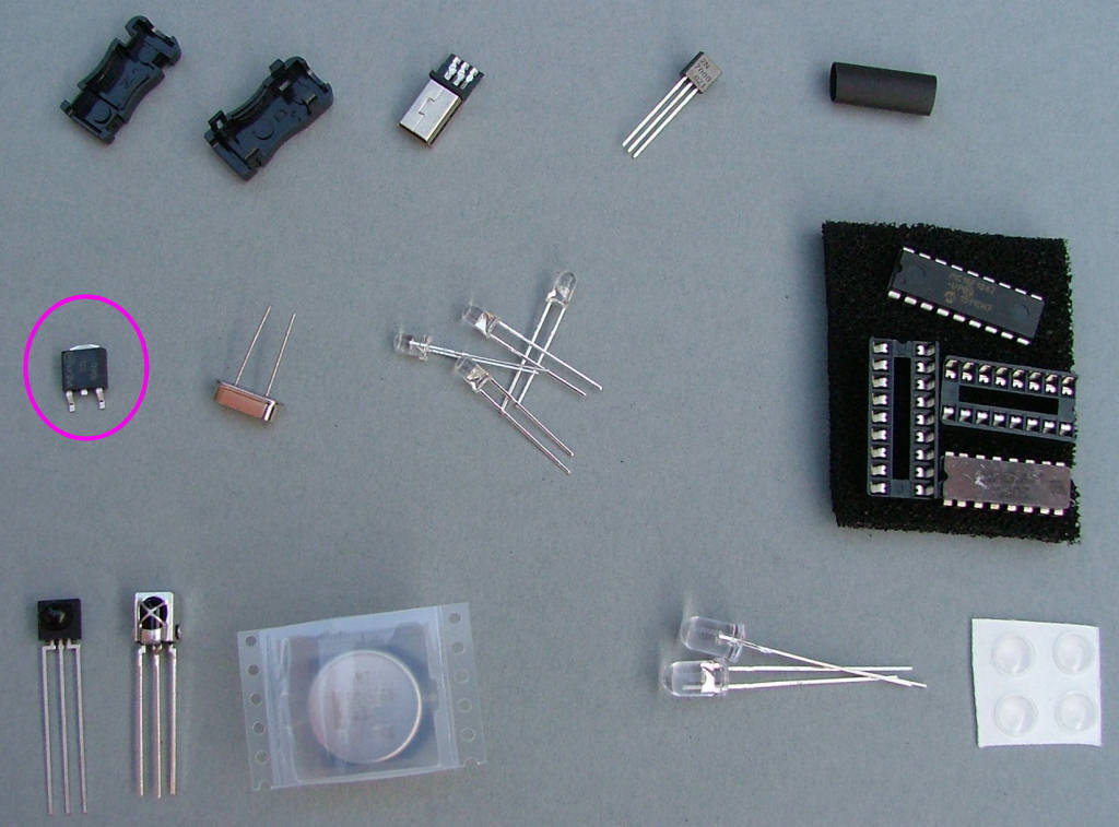
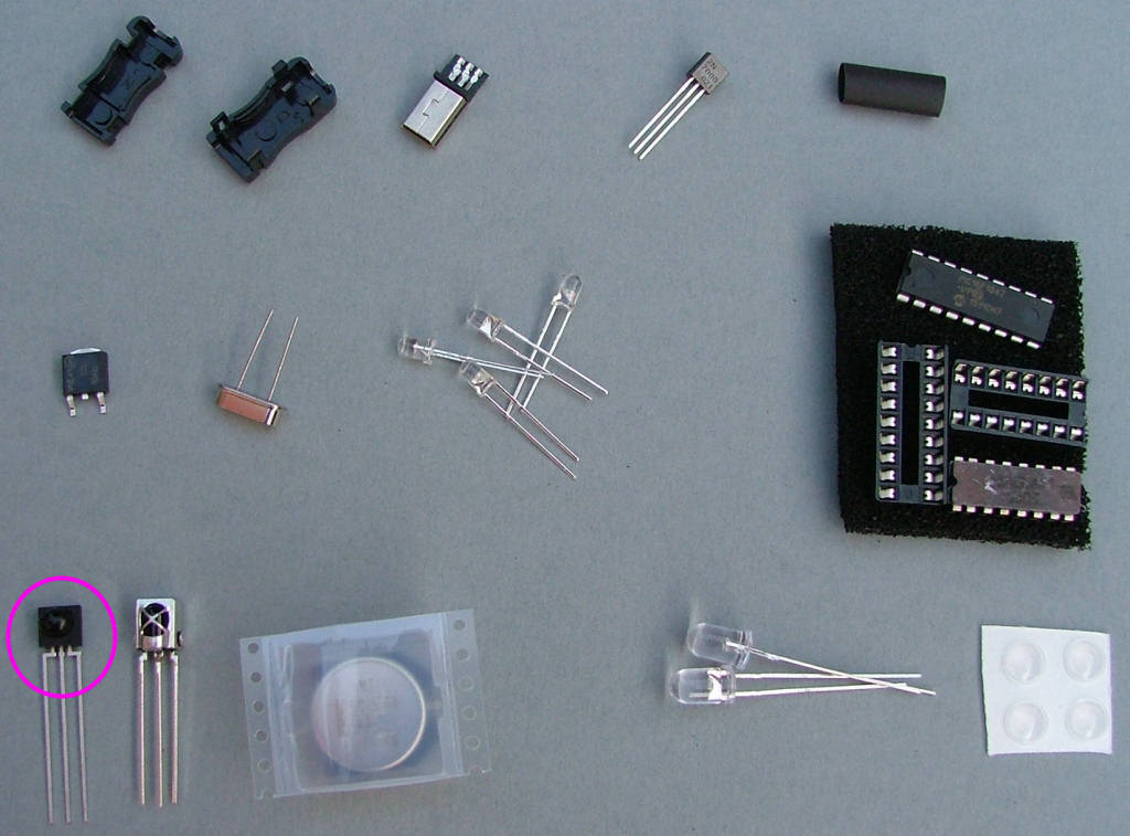
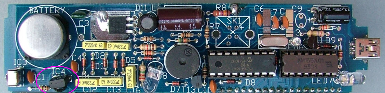
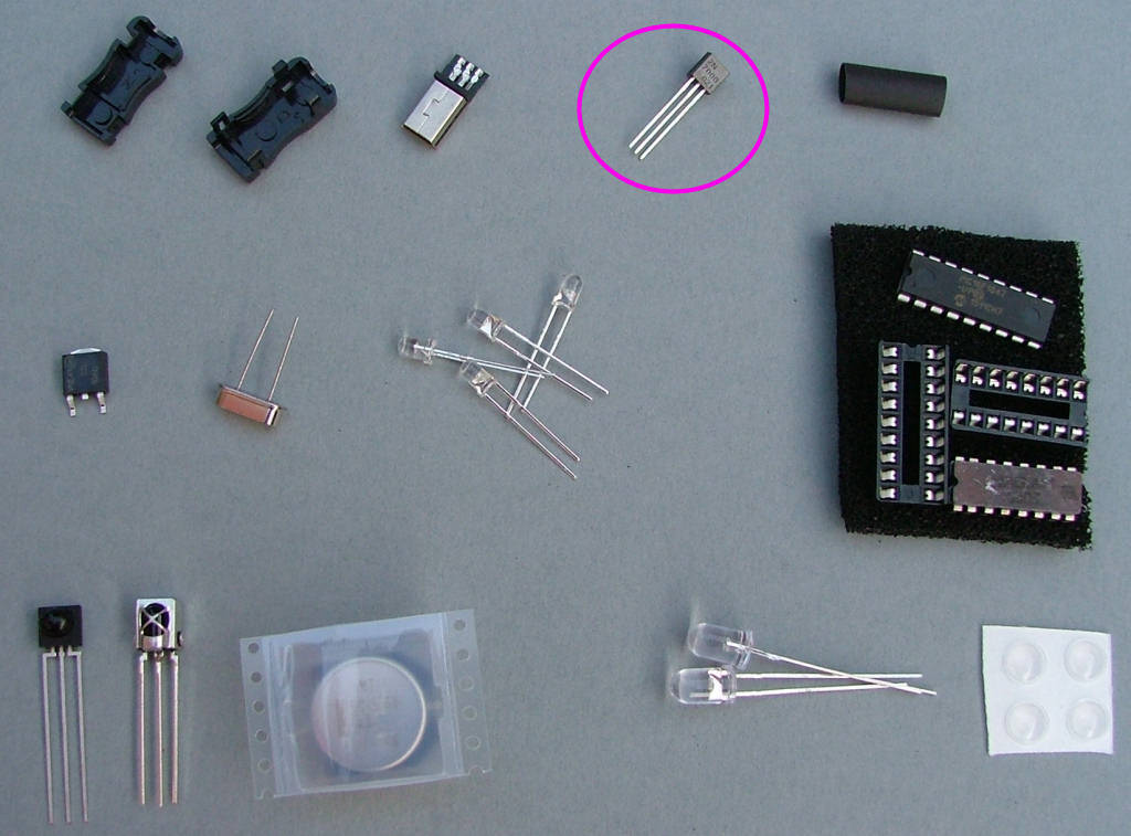
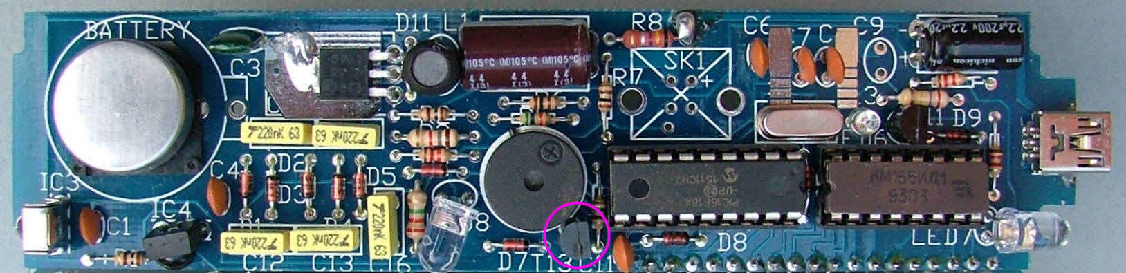
Fit T12 (the square black plastic 3 legged part), bending the end 3mm of its legs down 90 degrees to fit in the holes. Make sure it lies flat on the PCB and solder the tab on the top first, then the three legs. Some versions may have the centre leg missing, don't worry just solder the 2 outer legs and the tab.

DON'T FORGET TO SOLDER THE TAB! it acts as a heatsink connection to the PCB.

Image

Image
Tony
Site Admin
Posts: 949
Joined: Tue Jul 24, 2012 8:05 pm

Re: Clock PCB assembly

Post by Tony »

Fit the plastic IR LED in the space marked D8 as shown. NOTE this is polarised and must be fitted the right way round. There is a flat mark on the side of the LED body,

The flat side (Short leg) faces to the LEFT (LED8) of the PCB when viewed as shown in the photograph.

Image

Image
Tony
Site Admin
Posts: 949
Joined: Tue Jul 24, 2012 8:05 pm

Re: Clock PCB assembly

Post by Tony »

Fit IC4 as shown (the domed black plastic 3 legged block). IC4 is vertical and faces down. Twist it slightly to face to the right.

NOTE: As the orginal Sharp part is becoming harder to find it has been replaced with another silver metal-cased device, marked CHQ1838. IC4 will always be supplied in the pink antistatic bag.

Image

Image
Tony
Site Admin
Posts: 949
Joined: Tue Jul 24, 2012 8:05 pm

Re: Clock PCB assembly

Post by Tony »

Now fit T13 (2N7000) - it looks the same as T1-11 so is packed in the second bag to avoid it being mixed up. The flat edge faces RIGHT.

Image

Image
Locked