1- IR version PCB Assembly - Bag1
Posted: Sun Aug 03, 2014 1:06 am
First of all I should mention there are now 2 versions, one using the IR proximity sensor and one using two touchswitches for control. If you have a Bag1 labelled 'CLK501B' and your Bag2 contains 2 small red PCBs then you have the touchswitch version. They are almost identical but to avoid confusion it has its' own assembly threads prefixed 'BUTTON'. Please follow those rather than this one.
The exact order of assembly will depend on the preference of the builder but convention is to fit the resistors/diodes first followed by capacitors, transistors and ICs in that order.
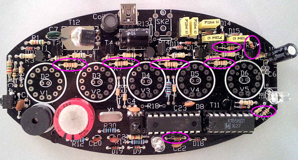
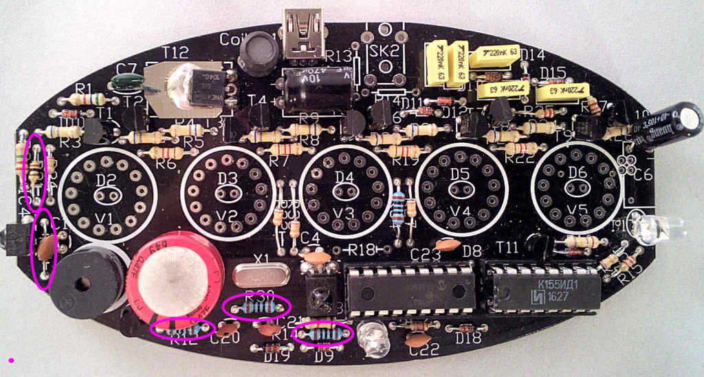
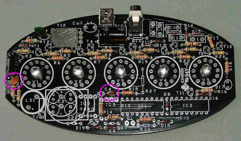
From November 2016 a new 'V2' PCB will be supplied with a few extra components. It's the second PCB picture and can be identified by component X1 being screen printed on the PCB under V2.
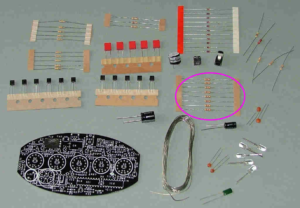
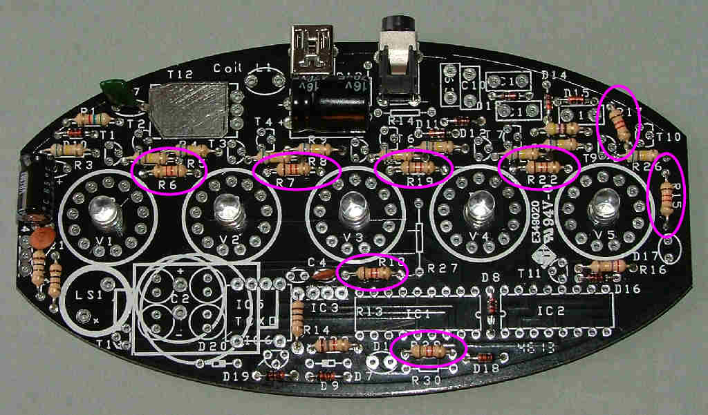
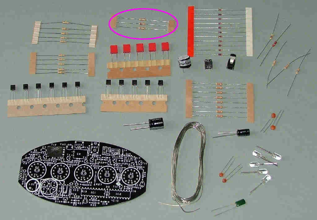
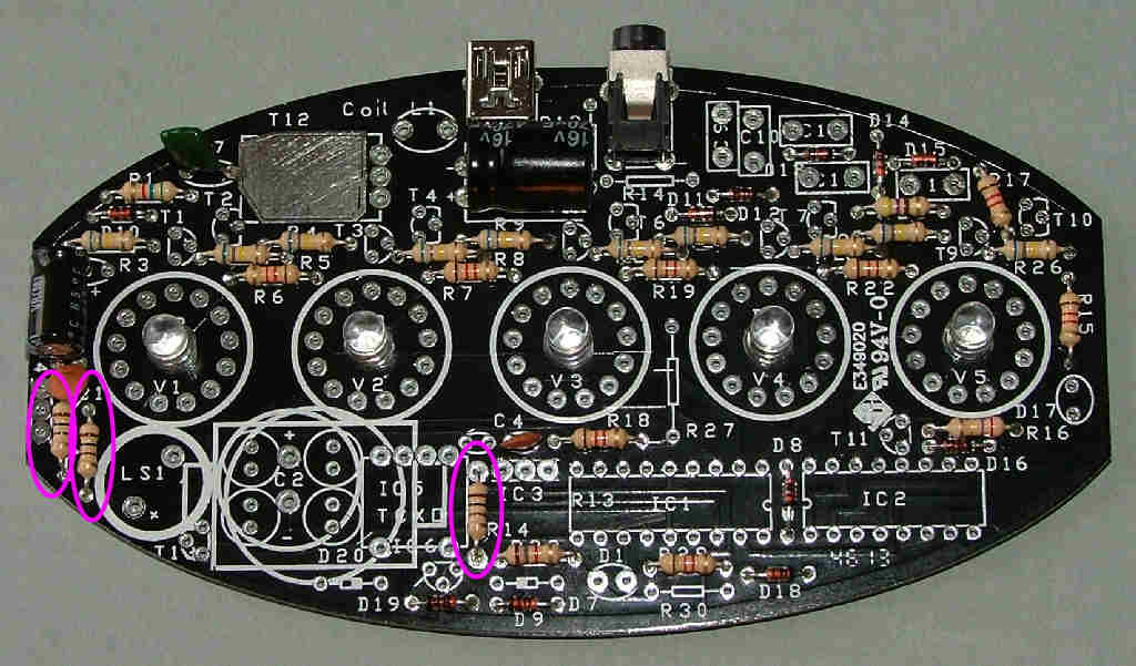
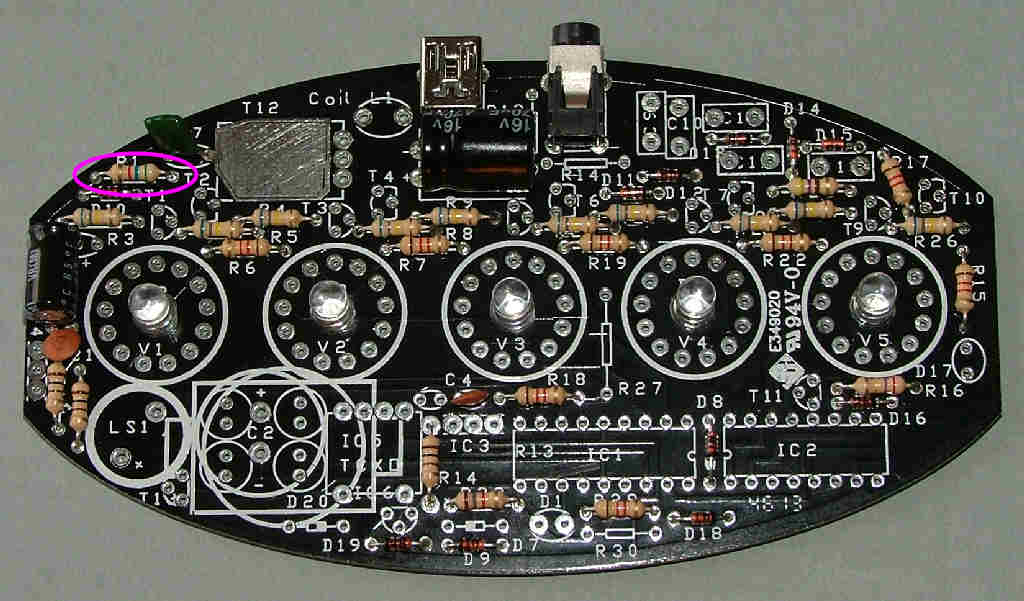
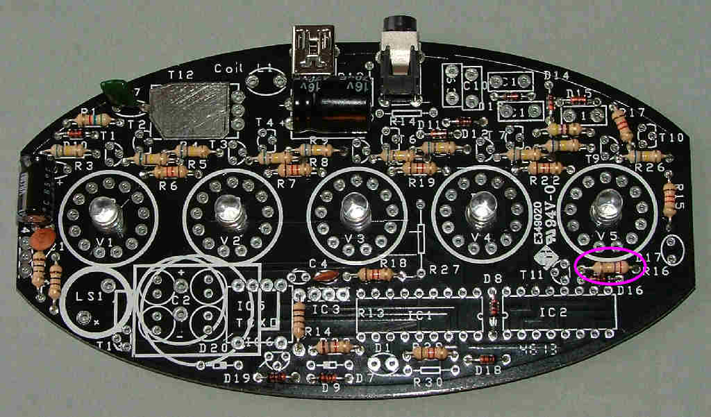
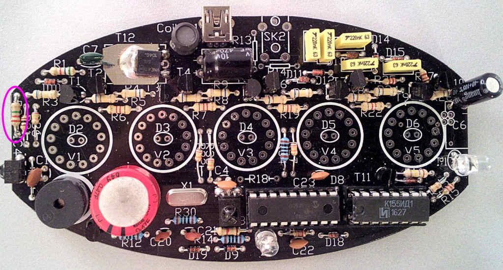
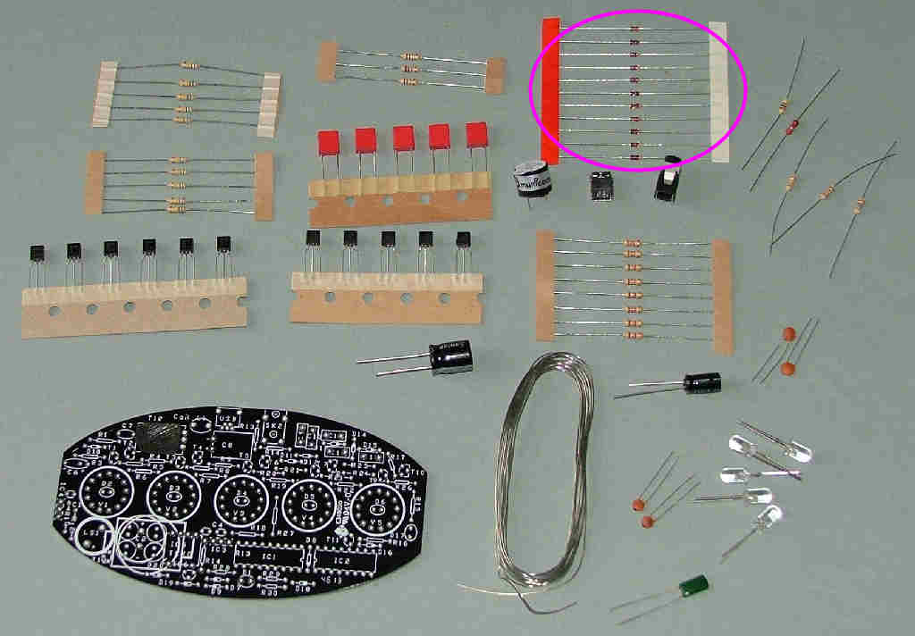
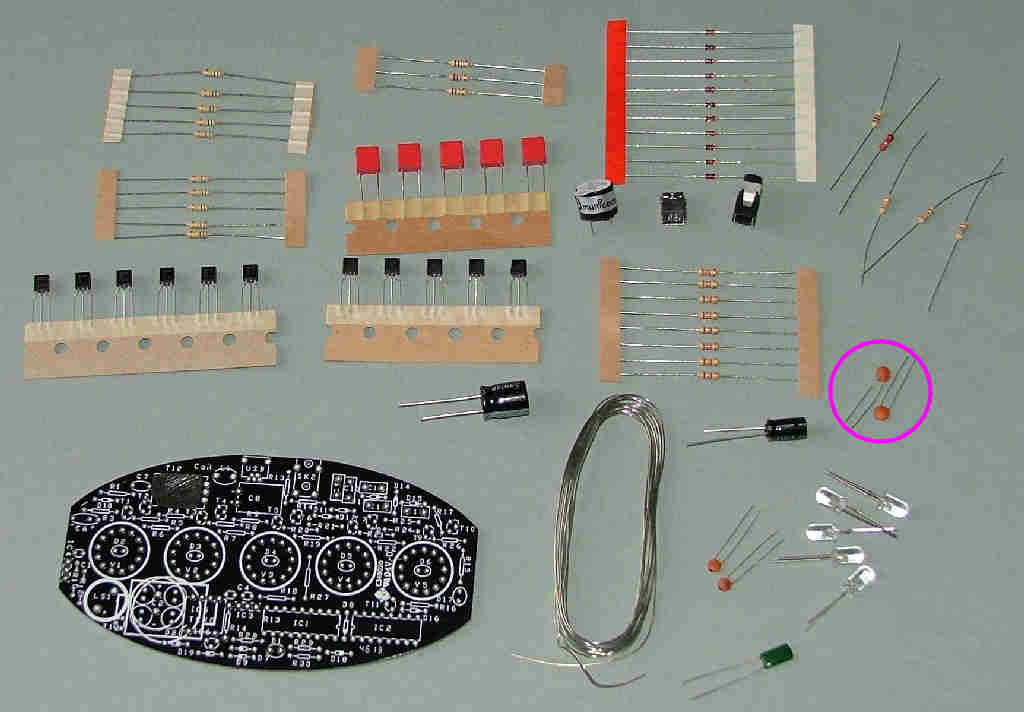
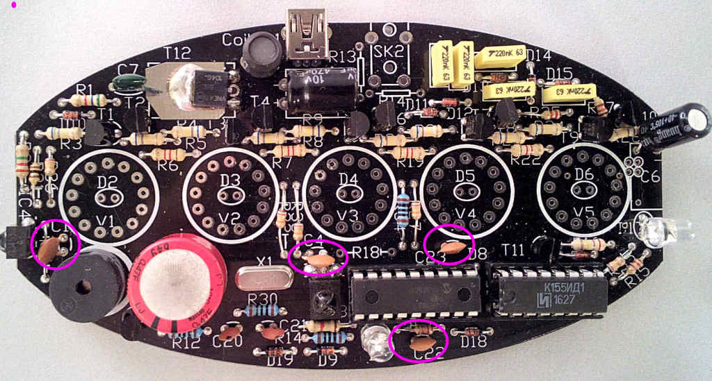
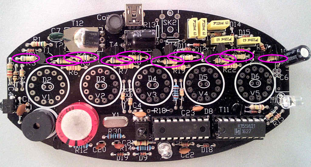
After preparing a suitable working space take the PCB and start with resistors R3,4,5,8,9,20,21,23,24 and 26. Over the years these have been 680k, (blue-grey-yellow) 560k (green blue yellow) and finally in the latest batch 2m2 (red red green). Fit these in locations marked for R3,4,5,8,9,20,21,23,24 and 26 as shown:


The exact order of assembly will depend on the preference of the builder but convention is to fit the resistors/diodes first followed by capacitors, transistors and ICs in that order.
From November 2016 a new 'V2' PCB will be supplied with a few extra components. It's the second PCB picture and can be identified by component X1 being screen printed on the PCB under V2.
After preparing a suitable working space take the PCB and start with resistors R3,4,5,8,9,20,21,23,24 and 26. Over the years these have been 680k, (blue-grey-yellow) 560k (green blue yellow) and finally in the latest batch 2m2 (red red green). Fit these in locations marked for R3,4,5,8,9,20,21,23,24 and 26 as shown: